
R0106-HP MSR Router Series Layer 2 - WAN Configuration Guide(V7)

49
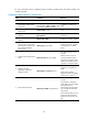
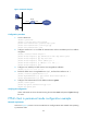
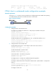
Figure 12 Network diagram
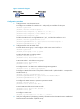
Configuration procedure
1. Create a PPPoE user.
<Router> system-view
[Router] local-user user1 class network
[Router-luser-network-user1] password simple pass1
[Router-luser-network-user1] service-type ppp
[Router-luser-network-user1] quit
2. Configure interface VT 1 to use CHAP for authentication and use an address pool for IP address
assignment.
[Router] interface virtual-template 1
[Router-Virtual-Template1] ppp authentication-mode chap domain system
[Router-Virtual-Template1] ppp chap user user1
[Router-Virtual-Template1] remote address pool 1
[Router-Virtual-Template1] ip address 1.1.1.1 255.0.0.0
[Router-Virtual-Template1] quit
3. Configure an IP address pool that contains nine assignable IP addresses.
[Router] ip pool 1 1.1.1.2 1.1.1.10
4. Enable the PPPoE server on GigabitEthernet 1/0/1, and bind the interface to VT 1.
[Router] interface gigabitethernet 1/0/1
[Router-GigabitEthernet1/0/1] pppoe-server bind virtual-template 1
[Router-GigabitEthernet1/0/1] quit
5. Configure local authentication for the default ISP domain system.
[Router] domain system
[Router-isp-system] authentication ppp local
[Router-isp-system] quit
Verifying the configuration
Host A and Host B can access the Internet using the username user1 and password pass1 through
the router.
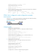
PPPoE client in permanent mode configuration example
Network requirements
As shown in Figure 13, Router A serves as a PPPoE server. Configure Router B as a PPPoE client operating
in permanent mode.
Internet
Router
S2/1/0
GE1/0/1
Host A
Host B