
R0106-HP MSR Router Series Layer 2 - WAN Configuration Guide(V7)

75
# Enable tunnel authentication, and specify the tunnel authentication key as aabbcc.
[LNS-l2tp1] tunnel authentication
[LNS-l2tp1] tunnel password simple aabbcc
[LNS-l2tp1] quit
3. On the remote system, enter vpdnuser as the username and Hello as the password in the dial-up
network window to dial a connection.
Verifying the configuration
After the dial-up connection is established, the remote system can obtain an IP address (for example,
192.168.0.2) and can ping the private IP address of the LNS (192.168.0.1).
# On the LNS, use the display l2tp tunnel command to check the established L2TP tunnels.
[LNS] display l2tp tunnel
LocalTID RemoteTID State Sessions RemoteAddress RemotePort RemoteName
196 3542 Established 1 1.1.2.1 1701 LAC
# On the LNS, use the display l2tp session command to check the established L2TP sessions.
[LNS] display l2tp session
LocalSID RemoteSID LocalTID State
2041 64 196 Established
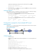
Configuration example for client-initiated L2TP tunnel
Network requirements
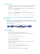
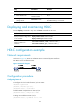
As shown in Figure 27, a PPP user directly initiates a tunneling request to the LNS to access the corporate
network. The PPP user belongs to VPN 1.
Figure 27 Network diagram
Configuration procedure
1. Configure the LNS:
# Create VPN instance vpn1, and bind interface GigabitEthernet 1/0/1 (connecting the PPP user)
to vpn1.
<LNS> system-view
[LNS] ip vpn-instance vpn1
[LNS-vpn-instance-vpn1] route-distinguisher 100:1
[LNS-vpn-instance-vpn1] vpn-target 111:1
[LNS-vpn-instance-vpn1] quit
[LNS] interface gigabitethernet 1/0/1
[LNS-GigabitEthernet1/0/1] ip binding vpn-instance vpn1
[LNS-GigabitEthernet1/0/1] quit
# Configure IP addresses for the interfaces. (Details not shown.)
# Configure the route between the LNS and the remote host. (Details not shown.)