
R0106-HP MSR Router Series MPLS Configuration Guide(V7)

233
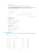
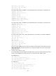
224.0.0.0/4 Direct 0 0 0.0.0.0 NULL0
224.0.0.0/24 Direct 0 0 0.0.0.0 NULL0
255.255.255.255/32 Direct 0 0 127.0.0.1 InLoop0
# Verify that CE 1 and CE 2 can ping each other. (Details not shown.)
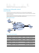
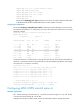
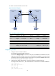
Configuring a hub-spoke network
Network requirements
The Spoke-CEs cannot communicate directly. They can communicate only through Hub-CE.
Configure EBGP between the Spoke-CEs and Spoke-PEs and between Hub-CE and Hub-PE to exchange
VPN routing information.
Configure OSPF between the Spoke-PEs and Hub-PE to implement communication between the PEs, and
configure MP-IBGP between them to exchange VPN routing information.
Figure 65 Network diagram
Table 14 Interface and IP assignment
Device Interface IP address
Device
Interface
IP address
Spoke-CE 1 GE2/1/1 10.1.1.1/24 Hub-CE GE2/1/1 10.3.1.1/24
Spoke-PE 1 Loop0 1.1.1.9/32 GE2/1/2 10.4.1.1/24
GE2/1/1 10.1.1.2/24 Hub-PE Loop0 2.2.2.9/32
POS2/1/0 172.1.1.1/24 POS2/1/0 172.1.1.2/24
Spoke-CE 2 GE2/1/1 10.2.1.1/24 POS2/1/1 172.2.1.2/24
Spoke-PE 2 Loop0 3.3.3.9/32 GE2/1/1 10.3.1.2/24
GE2/1/1 10.2.1.2/24 GE2/1/2 10.4.1.2/24
POS2/1/0 172.2.1.1/24