
R0106-HP MSR Router Series MPLS Configuration Guide(V7)

281
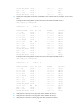
Device Interface IP address
Device
Interface
IP address
PE 1 Loop0 1.1.1.9/32 PE 2 Loop0 2.2.2.9/32
Loop1 3.3.3.3/32 Loop1 5.5.5.5/32
GE2/1/1 100.1.1.2/24 GE2/1/1 120.1.1.2/24
S2/1/1 10.1.1.1/24 S2/1/0 10.1.1.2/24
Router A S2/1/0 30.1.1.1/24
S2/1/1 20.1.1.2/24
Configuration procedure
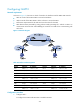
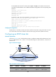
1. Configure OSPF on the customer networks.
Configure conventional OSPF on CE 1, Router A, and CE 2 to advertise addresses of the interfaces
as shown in Figure 72. Exec
ute the display ip routing-table command to verify that CE 1 and CE
2 have learned the route to each other. (Details not shown.)
2. Configure MPLS L3VPN on the backbone:
# Configure basic MPLS and MPLS LDP on PE 1 to establish LDP LSPs.
<PE1> system-view
[PE1] interface loopback 0
[PE1-LoopBack0] ip address 1.1.1.9 32
[PE1-LoopBack0] quit
[PE1] mpls lsr-id 1.1.1.9
[PE1] mpls ldp
[PE1-ldp] quit
[PE1] interface serial 2/1/1
[PE1-Serial2/1/1] ip address 10.1.1.1 24
[PE1-Serial2/1/1] mpls enable
[PE1-Serial2/1/1] mpls ldp enable
[PE1-Serial2/1/1] quit
# Configure PE 1 to take PE 2 as an MP-IBGP peer.
[PE1] bgp 100
[PE1-bgp] peer 2.2.2.9 as-number 100
[PE1-bgp] peer 2.2.2.9 connect-interface loopback 0
[PE1-bgp] address-family vpnv4
[PE1-bgp-vpnv4] peer 2.2.2.9 enable
[PE1-bgp-vpnv4] quit
[PE1-bgp] quit
# Configure OSPF on PE 1.
[PE1]ospf 1
[PE1-ospf-1]area 0
[PE1-ospf-1-area-0.0.0.0] network 1.1.1.9 0.0.0.0
[PE1-ospf-1-area-0.0.0.0] network 10.1.1.0 0.0.0.255
[PE1-ospf-1-area-0.0.0.0] quit
[PE1-ospf-1] quit
# Configure basic MPLS and MPLS LDP on PE 2 to establish LDP LSPs.
<PE2> system-view