HP MSR Router Series High Availability Configuration Guide(V7) Part number: 5998-5684 Software version: CMW710-R0106 Document version: 6PW100-20140607
Legal and notice information © Copyright 2014 Hewlett-Packard Development Company, L.P. No part of this documentation may be reproduced or transmitted in any form or by any means without prior written consent of Hewlett-Packard Development Company, L.P. The information contained herein is subject to change without notice.
Contents Configuring interface backup ····································································································································· 1 Overview············································································································································································ 1 Compatible interfaces ·····································································································································
Displaying and maintaining IPv6 VRRP··············································································································· 31 IPv4 VRRP configuration examples ······························································································································· 31 Single VRRP group configuration example ········································································································· 31 Multiple VRRP groups configuration example ·····
Configuring process placement policy ························································································································ 97 Configuring a location affinity ····························································································································· 97 Configuring a location type affinity····················································································································· 97 Configuring a process affinity ··
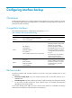
Configuring interface backup Overview Interface backup enables you to configure multiple backup interfaces for a Layer 3 interface to increase link availability. When the primary interface fails or is overloaded, its backup interfaces can take over or participate in traffic forwarding. Compatible interfaces The interface backup feature is configurable for the interfaces in Table 1.
Strict active/standby mode In strict active/standby mode, the primary interface always has higher priority than all backup interfaces. • When the primary interface is operating correctly, all traffic is transmitted through the primary interface. • When the primary interface fails, the highest-priority backup interface takes over. If the highest-priority backup interface also fails, the second highest-priority backup interface takes over, and so forth.
• When the primary interface fails (in DOWN state), the strict active/standby mode applies. Only one backup interface can forward traffic. The upper and lower thresholds are user configurable. NOTE: • "Traffic" on an interface refers to the amount of incoming or outgoing traffic, whichever is higher. • If two backup interfaces have the same priority, the one configured first has preference.
Interface backup configuration task list Task Remarks Configuring strict active/standby interface backup: You cannot use these two methods at the same time for a primary interface and its backup interfaces. • (Method 1.) Explicitly specifying backup interfaces without traffic thresholds • (Method 2.) Using interface backup with the Track module Use method 1 if you want to monitor the interface state of the primary interface for a switchover to occur.
Step Command Remarks 1. Enter system view. system-view N/A 2. Enter interface view. interface interface-type interface-number This interface must be the primary interface. 3. Specify a backup interface. backup interface interface-type interface-number [ priority ] 4. Set the switchover delay timers. backup timer delay up-delay down-delay By default, an interface does not have any backup interfaces. Repeat this command to specify up to three backup interfaces for the interface.
Step Command Remarks 1. Enter system view. system-view N/A 2. Enter interface view. interface interface-type interface-number This interface must be the interface you are using as a backup. 3. Associate the interface with a track entry. backup track track-entry-number By default, an interface is not associated with a track entry. Configuring load-shared interface backup To implement load-balanced interface backup, you must configure the traffic thresholds on the primary interface.
Task Command Display the status of primary and backup interfaces. display interface-backup state Interface backup configuration examples Strict active/standby interface backup configuration example Network requirements As shown in Figure 3: • Specify Serial 2/1/1 and Serial 2/1/2 on Router A to back up Serial 2/1/0. • Assign Serial 2/1/1 a higher priority than Serial 2/1/2. • Set the up and down delay timers to 10 seconds for the backup interfaces.
[RouterA-Serial2/1/0] backup interface serial 2/1/1 30 [RouterA-Serial2/1/0] backup interface serial 2/1/2 20 # Set both up and down delay timers to 10 seconds. [RouterA-Serial 2/1/0] backup timer delay 10 10 Verifying the configuration # Display states of the primary and backup interfaces.
Figure 4 Network diagram Configuration procedure 1. Assign IP addresses to interfaces, as shown in Figure 4. (Details not shown.) 2. Configure routes: # On Router A, configure static routes to 192.168.2.0/24 through the primary and backup interfaces. system-view [RouterA] ip route-static 192.168.2.0 24 serial 2/1/0 [RouterA] ip route-static 192.168.2.0 24 serial 2/1/1 # On Router B, configure static routes to 192.168.1.0/24. system-view [RouterB] ip route-static 192.168.1.
Load-shared interface backup configuration example Network requirements As shown in Figure 5: • Configure Serial 2/1/1 and Serial 2/1/2 on Router A to back up the primary interface Serial 2/1/0. • Assign Serial 2/1/1 higher priority than Serial 2/1/2. • On the primary interface: { Specify the interface bandwidth used for traffic load calculation. { Set the upper and lower thresholds to 80 and 20, respectively. Figure 5 Network diagram Configuration procedure 1.
# Set the upper and lower thresholds to 80 and 20, respectively. [RouterA-Serial2/1/0] backup threshold 80 20 Verifying the configuration # Display traffic statistics for load-shared interfaces.
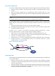
Configuring VRRP Overview Typically, you can configure a default gateway for every host on a LAN. All packets destined for other networks are sent through the default gateway. As shown in Figure 6, when the default gateway fails, no hosts can communicate with external networks. Figure 6 LAN networking Using a default gateway facilitates your configuration but requires high availability. Using more egress gateways improves link availability but introduces the problem of routing among the egresses.
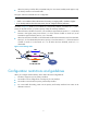
VRRP standard mode In VRRP standard mode, only the master in the VRRP group can provide gateway service. When the master fails, the backup routers elect a new master to take over for nonstop gateway service. Figure 7 VRRP networking As shown in Figure 7, Router A, Router B, and Router C form a virtual router, which has its own IP address. Hosts on the subnet use the virtual router as the default gateway.
Authentication method To avoid attacks from unauthorized users, VRRP member routers add authentication keys in VRRP packets to authenticate one another. VRRP provides the following authentication methods: • Simple authentication The sender fills an authentication key into the VRRP packet, and the receiver compares the received authentication key with its local authentication key. If the two authentication keys match, the received VRRP packet is legitimate.
Master election Routers in a VRRP group determine their roles by priority. When a router joins a VRRP group, it has a backup role. The router role changes according to the following situations: • If the backup does not receive any VRRP advertisement when the timer (3 × advertisement interval + Skew_Time) expires, it becomes the master. • If the backup receives a VRRP advertisement with a greater or the same priority within the timer (3 × advertisement interval + Skew_Time), it remains a backup.
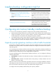
Figure 8 VRRP in master/backup mode Assume that Router A is acting as the master to forward packets to external networks, and Router B and Router C are backups in listening state. When Router A fails, Router B and Router C elect a new master to forward packets for hosts on the subnet. Load sharing A router can join multiple VRRP groups and has different priorities in different VRRP groups, and it can act as the master in one VRRP group and a backup in another.
• VRRP group 1—Router A is the master. Router B and Router C are the backups. • VRRP group 2—Router B is the master. Router A and Router C are the backups. • VRRP group 3—Router C is the master. Router A and Router B are the backups. To implement load sharing among Router A, Router B, and Router C, hosts on the subnet must be configured with the virtual IP addresses of VRRP group 1, 2, and 3 as default gateways, respectively.
Figure 10 Virtual MAC address assignment Network Router A Master Virtual MAC: 000f-e2ff-0011 Virtual IP address:10.1.1.1/24 Router B Backup Virtual MAC: 000f-e2ff-0012 Virtual IP address:10.1.1.1/24 Allocate Virtual MAC 000f-e2ff-0012 to Router B Gateway IP: 10.1.1.1/24 Gateway IP: 10.1.1.1/24 Host A 2. Host B When an ARP request arrives, the master (Router A) selects a virtual MAC address based on the load balancing algorithm to answer the ARP request.
Figure 12 Sending packets to different routers for forwarding Virtual forwarder Virtual forwarder creation Virtual MAC addresses enable traffic distribution across routers in a VRRP group. To enable routers in the VRRP group to forward packets, VFs must be created on them. Each VF is associated with a virtual MAC address in the VRRP group and forwards packets that are sent to this virtual MAC address. VFs are created on routers in a VRRP group, as follows: 1.
• If the weight of the VF is lower than the lower limit of failure, the priority of the VF is 0. VF backup The VFs corresponding to a virtual MAC address on different routers in the VRRP group back up one another. Figure 13 VF information Figure 13 shows the VF table on each router in the VRRP group and how the VFs back up one another.
the master stops using the virtual MAC address corresponding to the failed AVF to respond to ARP/ND requests from hosts. Timeout timer—The duration after which the new AVF takes over responsibilities of the failed VF owner. Before this timer expires, all routers in the VRRP group keep the VFs that correspond to the failed AVF. The new AVF forwards packets destined for the virtual MAC address of the failed AVF.
• Standard mode—Only the master can forward packets. • Load balancing mode—All members that have an AVF can forward packets. After an IPv4 VRRP operating mode is configured on a router, all IPv4 VRRP groups on the router operate in the specified operating mode. To specify an IPv4 VRRP operating mode: Step Command Remarks 1. Enter system view. system-view N/A • Specify the standard mode: 2. Specify an IPv4 operating mode.
• When a router is the IP address owner in a VRRP group, do not configure the network command on the interface to use the IP address of the interface, or the virtual IP address of the VRRP group, to establish a neighbor relationship with the adjacent router. For more information about the network command, see Layer 3—IP Routing Command Reference. • If you create an IPv4 VRRP group but do not assign any virtual IP address for it, the VRRP group stays in inactive state and does not function.
Step Command Remarks 4. Enable the preemptive mode for the router in a VRRP group and configure the preemption delay time. vrrp vrid virtual-router-id preempt-mode [ delay delay-value ] By default, the router in a VRRP group operates in preemptive mode and the preemption delay time is 0 seconds, which means an immediate preemption. 5. Associate a VRRP group with a track entry.
Step Command Remarks 5. Specify the source interface for receiving and sending VRRP packets. vrrp vrid virtual-router-id source-interface interface-type interface-number By default, the source interface for receiving and sending VRRP packets is not specified. The interface where the VRRP group resides sends and receives VRRP packets. 6. Enable TTL check for IPv4 VRRP packets. vrrp check-ttl enable By default, TTL check for IPv4 VRRP packets is enabled. 7. Return to system view.
Enabling SNMP notifications for VRRP Perform this task to enable VRRP to report important events through notifications to the SNMP module. The SNMP module determines how to output the notifications according to the configured output rules. For more information about notifications, see Network Management and Monitoring Configuration Guide. To enable SNMP notifications for VRRP: Step Command Remarks 1. Enter system view. system-view N/A 2. Enable SNMP notifications for VRRP.
IPv6 VRRP configuration task list Tasks at a glance Remarks (Required.) Specifying an IPv6 VRRP operating mode N/A (Required.) Creating a VRRP group and assigning a virtual IPv6 address N/A (Optional.) Configuring the router priority, preemptive mode, and tracking function N/A (Optional.) Configuring VF tracking This configuration applies to only VRRP load balancing mode. (Optional.) Configuring IPv6 VRRP packet attributes N/A (Optional.
• In load balancing mode, the virtual IPv6 address of a VRRP group cannot be the same as the IPv6 address of any interface in the VRRP group. • The maximum number of VRRP groups that you can create on an interface is 16. The maximum number of virtual IPv6 addresses that you can assign to a VRRP group is 16. • In VRRP load balancing mode, the device supports a maximum of MaxVRNum/N VRRP groups.
Configuration procedure To configure the router priority, preemptive mode, and tracking function: Step Command Remarks 1. Enter system view. system-view N/A 2. Enter interface view. interface interface-type interface-number N/A 3. Configure the priority of the router in the VRRP group. vrrp ipv6 vrid virtual-router-id priority priority-value The default setting is 100. 4. Enable the preemptive mode for the router in a VRRP group and configure the preemption delay time.
Configuring IPv6 VRRP packet attributes This section describes how to configure IPv6 VRRP packet attributes. Configuration guidelines • The routers in an IPv6 VRRP group can have different intervals for sending VRRP advertisements. The master in the VRRP group sends VRRP advertisements at the specified interval and carries the interval attribute in the advertisements. After a backup receives the advertisement, it records the interval in the advertisement.
Step Command Remarks 3. Disable an IPv6 VRRP group. vrrp ipv6 vrid virtual-router-id shutdown By default, an IPv6 VRRP group is enabled. Displaying and maintaining IPv6 VRRP Execute display commands in any view and the reset command in user view. Task Command Display the states of IPv6 VRRP groups. display vrrp ipv6 [ interface interface-type interface-number [ vrid virtual-router-id ] ] [ verbose ] Display statistics for IPv6 VRRP groups.
Configuration procedure 1. Configure Router A: # Specify an IP address for Router A. system-view [RouterA] interface gigabitethernet 2/0/1 [RouterA-GigabitEthernet2/0/1] ip address 10.1.1.1 255.255.255.0 # Create VRRP group 1 on GigabitEthernet 2/0/1 and set its virtual IP address to 10.1.1.111. [RouterA-GigabitEthernet2/0/1] vrrp vrid 1 virtual-ip 10.1.1.111 # Assign Router A a higher priority than Router B in VRRP group 1, so Router A can become the master.
Total number of virtual routers : 1 Interface GigabitEthernet2/0/1 VRID : 1 Adver Timer : 100 Admin Status : Up State : Backup Config Pri : 100 Running Pri : 100 Preempt Mode : Yes Delay Time : 5 Become Master : 412ms left Auth Type : None Virtual IP : 10.1.1.111 Master IP : 10.1.1.1 The output shows that Router A is operating as the master in VRRP group 1 to forward packets from Host A to Host B.
Multiple VRRP groups configuration example To implement load sharing between the VRRP groups, you must manually configure the default gateway 10.1.1.111 for some hosts and 10.1.1.112 for the other on the subnet 10.1.1.0/24. Network requirements Router A and Router B form two VRRP groups to implement load sharing and mutual backup. VRRP group 1 uses the virtual IP address 10.1.1.111/24 to provide gateway service for some hosts on the subnet 10.1.1.0/24, and VRRP group 2 uses the virtual IP address 10.1.1.
[RouterB-GigabitEthernet2/0/1] vrrp vrid 1 virtual-ip 10.1.1.111 # Create VRRP group 2, and set its virtual IP address to 10.1.1.112. [RouterB-GigabitEthernet2/0/1] vrrp vrid 2 virtual-ip 10.1.1.112 # Assign Router B a higher priority than Router A in VRRP group 2, so Router B can become the master in the group. [RouterB-GigabitEthernet2/0/1] vrrp vrid 2 priority 110 3. Verify the configuration: # Display detailed information about the VRRP groups on Router A.
VRID : 2 Adver Timer : 100 Admin Status : Up State : Master Config Pri : 110 Running Pri : 110 Preempt Mode : Yes Delay Time : 0 Auth Type : None Virtual IP : 10.1.1.112 Virtual MAC : 0000-5e00-0102 Master IP : 10.1.1.2 The output shows that Router A is operating as the master in VRRP group 1 to forward Internet traffic for hosts that use the default gateway 10.1.1.
system-view [RouterA] vrrp mode load-balance # Create VRRP group 1, and set its virtual IP address to 10.1.1.1. [RouterA] interface gigabitethernet 2/0/1 [RouterA-GigabitEthernet2/0/1] ip address 10.1.1.2 24 [RouterA-GigabitEthernet2/0/1] vrrp vrid 1 virtual-ip 10.1.1.1 # Assign Router A the highest priority in VRRP group 1, so Router A can become the master.
[RouterC] interface gigabitethernet 2/0/1 [RouterC-GigabitEthernet2/0/1] ip address 10.1.1.4 24 [RouterC-GigabitEthernet2/0/1] vrrp vrid 1 virtual-ip 10.1.1.1 # Configure Router C to operate in preemptive mode, and set the preemption delay to 5 seconds. [RouterC-GigabitEthernet2/0/1] vrrp vrid 1 preempt-mode delay 5 [RouterC-GigabitEthernet2/0/1] quit # Create track entry 1 to monitor the upstream link status of GigabitEthernet 2/0/2. When the upstream link fails, the track entry transits to Negative.
Virtual MAC : 000f-e2ff-0013 (Learnt) Owner ID : 0000-5e01-1105 Priority : 127 Active : 10.1.1.4 Forwarder Weight Track Information: Track Object : 1 State : Positive Weight Reduced : 250 # Display detailed information about VRRP group 1 on Router B.
Running Mode : Load Balance Total number of virtual routers : 1 Interface GigabitEthernet2/0/1 VRID : 1 Adver Timer : 100 Admin Status : Up State : Backup Config Pri : 100 Running Pri : 100 Preempt Mode : Yes Delay Time : 5 Become Master : 417ms left Auth Type : None Virtual IP : 10.1.1.1 Member IP List : 10.1.1.4 (Local, Backup) 10.1.1.2 (Master) 10.1.1.
Preempt Mode : Yes Auth Type : None Virtual IP : 10.1.1.1 Delay Time : 5 Member IP List : 10.1.1.2 (Local, Master) 10.1.1.3 (Backup) 10.1.1.4 (Backup) Forwarder Information: 3 Forwarders 0 Active Config Weight : 255 Running Weight : 5 Forwarder 01 State : Initialize Virtual MAC : 000f-e2ff-0011 (Owner) Owner ID : 0000-5e01-1101 Priority : 0 Active : 10.1.1.4 Forwarder 02 State : Initialize Virtual MAC : 000f-e2ff-0012 (Learnt) Owner ID : 0000-5e01-1103 Priority : 0 Active : 10.
Forwarder 01 State : Active Virtual MAC : 000f-e2ff-0011 (Take Over) Owner ID : 0000-5e01-1101 Priority : 85 Active : local Forwarder 02 State : Listening Virtual MAC : 000f-e2ff-0012 (Learnt) Owner ID : 0000-5e01-1103 Priority : 85 Active : 10.1.1.
Active : 10.1.1.3 Forwarder 03 State : Active Virtual MAC : 000f-e2ff-0013 (Owner) Owner ID : 0000-5e01-1105 Priority : 255 Active : local Forwarder Weight Track Information: Track Object : 1 State : Positive Weight Reduced : 250 The output shows that when the timeout timer expires, the VF for virtual MAC address 000f-e2ff-0011 is removed, and no longer forwards the packets destined for the MAC address. # When Router A fails, display detailed information about VRRP group 1 on Router B.
IPv6 VRRP configuration examples Single VRRP group configuration example Network requirements Router A and Router B form a VRRP group, and use the virtual IP addresses 1::10/64 and FE80::10 to provide gateway service for the subnet where Host A resides, as shown in Figure 17. Host A learns 1::10/64 as its default gateway from RA messages sent by the routers. Router A operates as the master to forward packets from Host A to Host B. When Router A fails, Router B takes over to forward packets for Host A.
2. Configure Router B: # Specify an IPv6 address for Router B. system-view [RouterB] interface gigabitethernet 2/0/1 [RouterB-GigabitEthernet2/0/1] ipv6 address fe80::2 link-local [RouterB-GigabitEthernet2/0/1] ipv6 address 1::2 64 # Create VRRP group 1, and set its virtual IPv6 addresses to FE80::10 and 1::10.
The output shows that Router A is operating as the master in VRRP group 1 to forward packets from Host A to Host B. # Disconnect the link between Host A and Router A, and verify that Host A can still ping Host B. (Details not shown.) # Display detailed information about VRRP group 1 on Router B.
and VRRP group 2 uses the virtual IP address 1::20/64 to provide gateway service for the other hosts on the subnet, as shown in Figure 18. Figure 18 Network diagram Configuration procedure 1. Configure Router A: # Specify an IPv6 address for Router A.
# Create VRRP group 2, and set its virtual IPv6 addresses to FE80::20 and 1::20. [RouterB-GigabitEthernet2/0/1] vrrp ipv6 vrid 2 virtual-ip fe80::20 link-local [RouterB-GigabitEthernet2/0/1] vrrp ipv6 vrid 2 virtual-ip 1::20 # Assign Router B a higher priority than Router A in VRRP group 2, so Router B can become the master in the group. [RouterB-GigabitEthernet2/0/1] vrrp ipv6 vrid 2 priority 110 3. Verify the configuration: # Display detailed information about the VRRP groups on Router A.
Interface GigabitEthernet2/0/1 VRID : 2 Adver Timer : 100 Admin Status : Up State : Master Config Pri : 110 Running Pri : 110 Preempt Mode : Yes Delay Time : 0 Auth Type : None Virtual IP : FE80::20 Virtual MAC : 0000-5e00-0202 Master IP : FE80::2 1::20 The output shows that Router A is operating as the master in VRRP group 1 to forward Internet traffic for hosts that use the default gateway 1::10/64.
Configuration procedure 1. Configure Router A: # Configure VRRP to operate in load balancing mode. system-view [RouterA] vrrp ipv6 mode load-balance # Create VRRP group 1, and set its virtual IPv6 addresses to FE80::10 and 1::10.
[RouterB-GigabitEthernet2/0/1] quit # Create track entry 1 to monitor the upstream link status of GigabitEthernet 2/0/2. When the upstream link fails, the track entry transits to Negative. [RouterB] track 1 interface gigabitethernet 2/0/2 # Configure the VFs in VRRP group 1 to monitor track entry 1, and decrease their weights by 250 when the track entry transits to Negative. [RouterB] interface gigabitethernet 2/0/1 [RouterB-GigabitEthernet2/0/1] vrrp ipv6 vrid 1 weight track 1 reduced 250 3.
Member IP List : FE80::1 (Local, Master) FE80::2 (Backup) FE80::3 (Backup) Forwarder Information: 3 Forwarders 1 Active Config Weight : 255 Running Weight : 255 Forwarder 01 State : Active Virtual MAC : 000f-e2ff-4011 (Owner) Owner ID : 0000-5e01-1101 Priority : 255 Active : local Forwarder 02 State : Listening Virtual MAC : 000f-e2ff-4012 (Learnt) Owner ID : 0000-5e01-1103 Priority : 127 Active : FE80::2 Forwarder 03 State : Listening Virtual MAC : 000f-e2ff-4013 (Learnt) Owner ID
Virtual MAC : 000f-e2ff-4011 (Learnt) Owner ID : 0000-5e01-1101 Priority : 127 Active : FE80::1 Forwarder 02 State : Active Virtual MAC : 000f-e2ff-4012 (Owner) Owner ID : 0000-5e01-1103 Priority : 255 Active : local Forwarder 03 State : Listening Virtual MAC : 000f-e2ff-4013 (Learnt) Owner ID : 0000-5e01-1105 Priority : 127 Active : FE80::3 Forwarder Weight Track Information: Track Object : 1 State : Positive Weight Reduced : 250 # Display detailed information about VRRP gro
Priority : 127 Active : FE80::2 Forwarder 03 State : Active Virtual MAC : 000f-e2ff-4013 (Owner) Owner ID : 0000-5e01-1105 Priority : 255 Active : local Forwarder Weight Track Information: Track Object : 1 State : Positive Weight Reduced : 250 The output shows that Router A is the master in VRRP group 1, and each of the three routers has one AVF and two LVFs. # Disconnect the link of GigabitEthernet 2/0/2 on Router A, and display detailed information about VRRP group 1 on Router A.
Priority : 0 Active : FE80::3 Forwarder Weight Track Information: Track Object : 1 State : Negative Weight Reduced : 250 # Display detailed information about VRRP group 1 on Router C.
# When the timeout timer (about 1800 seconds) expires, display detailed information about VRRP group 1 on Router C.
Virtual IP : FE80::10 1::10 Member IP List : FE80::2 (Local, Master) FE80::3 (Backup) Forwarder Information: 2 Forwarders 1 Active Config Weight : 255 Running Weight : 255 Forwarder 02 State : Active Virtual MAC : 000f-e2ff-4012 (Owner) Owner ID : 0000-5e01-1103 Priority : 255 Active : local Forwarder 03 State : Listening Virtual MAC : 000f-e2ff-4013 (Learnt) Owner ID : 0000-5e01-1105 Priority : 127 Active : FE80::3 Forwarder Weight Track Information: Track Object : 1 State : Posit
Multiple masters appear in a VRRP group Symptom Multiple masters appear in a VRRP group. Analysis It is normal for a VRRP group to have multiple masters for a short time, and this situation requires no manual intervention. If multiple masters coexist for a longer period, it might be because the masters cannot receive advertisements from each other, or because the received advertisements are illegitimate.
Configuring BFD Overview Bidirectional forwarding detection (BFD) provides a general-purpose, standard, medium- and protocol-independent fast failure detection mechanism. It can detect and monitor the connectivity of links in IP to detect communication failures quickly so that measures can be taken to ensure service continuity and enhance network availability.
Echo packet mode The local end of the link sends echo packets to establish BFD sessions and monitor link status. The peer end does not establish BFD sessions and only forwards the packets back to the originating end. In echo packet mode, BFD supports only single-hop detection and the BFD session is independent of the operating mode. Control packet mode Both ends of the link exchange BFD control packets to monitor link status.
Protocols and standards • RFC 5880, Bidirectional Forwarding Detection (BFD) • RFC 5881, Bidirectional Forwarding Detection (BFD) for IPv4 and IPv6 (Single Hop) • RFC 5882, Generic Application of Bidirectional Forwarding Detection (BFD) • RFC 5883, Bidirectional Forwarding Detection (BFD) for Multihop Paths • RFC 5884, Bidirectional Forwarding Detection (BFD) for MPLS Label Switched Paths (LSPs) • RFC 5885, Bidirectional Forwarding Detection (BFD) for the Pseudowire Virtual Circuit Connectivity V
Step Command Remarks 5. (Optional.) Configure the single-hop detection time multiplier. bfd detect-multiplier value The default setting is 5. Configuring control packet mode To configure control packet mode for single-hop detection: Step Command Remarks 1. Enter system view. system-view N/A 2. Specify the mode for establishing a BFD session. bfd session init-mode { active | passive } By default, active is specified. 3. Enter interface view. interface interface-type interface-number N/A 4.
Step Command Remarks 3. Configure the authentication mode for multihop BFD control packets. bfd multi-hop authentication-mode simple key-id { cipher cipher-string | plain plain-string } By default, no authentication is performed. 4. Configure the destination port number for multihop BFD control packets. bfd multi-hop destination-port port-number The default setting is 4784. 5. Configure the multihop detection time multiplier. bfd multi-hop detect-multiplier value The default setting is 5. 6.
Configuring Track Overview The Track module works between application modules and detection modules, as shown in Figure 20. It shields the differences between various detection modules from application modules. Collaboration is enabled after you associate the Track module with a detection module and an application module. The detection module probes objects such as interface status, link status, network reachability, and network performance, and informs the Track module of detection results.
Collaboration between the Track module and an application module The following application modules can be associated with the Track module: • VRRP. • Static routing. • Policy-based routing (PBR). • Interface backup. When configuring a track entry for an application module, you can set a notification delay to avoid immediate notification of status changes. This helps prevent communication failure when the when route convergence is slower than the link state change notification.
Tasks at a glance Remarks (Required.) Associating the Track module with an application module: • • • • Associating Track with VRRP Use one of the methods. Associating Track with static routing Associating Track with PBR Associating Track with interface backup Associating the Track module with a detection module Associating Track with NQA NQA supports multiple operation types to analyze network performance, services, and service quality.
• If the BFD detects that the link is operating correctly, the Track module sets the track entry to Positive state. Configuration prerequisites Before you associate Track with BFD, configure the source IP address of BFD echo packets. For more information, see "Configuring BFD." Configuration procedure To associate Track with BFD: Step Command Remarks 1. Enter system view. system-view N/A 2.
Step Command Remarks • Create a track entry, and associate it 2. Associate Track with interface management.
An IP address owner is the router with its interface IP address used as the virtual IP address of the VRRP group. • When the status of the track entry changes from Negative to Positive or NotReady, the associated router or VF restores its priority automatically. • You can associate a nonexistent track entry with a VRRP group or VF. The association takes effect only after you use the track command to create the track entry. Associating Track with a VRRP group Step Command Remarks 1. Enter system view.
If you specify the next hop but not the egress interface when configuring a static route, you can establish collaborations among the static route, the Track module, and detection modules. This enables you to check the accessibility of the static route by the status of the track entry. • The Positive state of the track entry shows that the next hop of the static route is reachable, and that the configured static route is valid.
ACLs or have specific lengths. For more information about PBR, see Layer 3—IP Routing Configuration Guide. PBR cannot detect the availability of any action taken on packets. When an action is not available, packets processed by the action might be discarded. For example, configure PBR to forward packets that match certain criteria through a user-specified interface. When the link of the interface fails, PBR cannot sense the failure, and continues to forward matching packets out of the interface.
Step Command Remarks • Set the output interface, and associate it with a track entry: apply output-interface { interface-type interface-number [ track track-entry-number ] }&<1-n> • Set the next hop, and associate it with a 4. Associate Track with PBR. track entry: apply next-hop [ vpn-instance vpn-instance-name | inbound-vpn ] { ip-address [ direct ] [ track track-entry-number ] }&<1-n> • Set the default output interface, and Use at least one of the commands.
Step Command Remarks • Set the output interface, and associate it with a track entry: apply output-interface { interface-type interface-number [ track track-entry-number ] }&<1-n> • Set the next hop, and associate it with a 4. Associate Track with IPv6 PBR. track entry: apply next-hop [ vpn-instance vpn-instance-name | inbound-vpn ] { ipv6-address [ direct ] [ track track-entry-number ] }&<1-n> • Set the default output interface, and Use at least one of the commands.
Step Command Remarks Not configured by default. 3. Associate the interface with a track entry. backup track track-entry-number You can only associate one interface with a track entry. If you use this command multiple times, the most recent configuration takes effect. Displaying and maintaining track entries Execute display commands in any view. Task Command Display information about a specific or all track entries.
Configuration procedure 1. Configure the IP address of each interface as shown in Figure 21. (Details not shown.) 2. Configure an NQA operation on Router A: # Create an NQA operation with the administrator name admin and the operation tag test. system-view [RouterA] nqa entry admin test # Configure the operation type as ICMP echo. [RouterA-nqa-admin-test] type icmp-echo # Configure the destination address as 10.1.2.2. [RouterA-nqa-admin-test-icmp-echo] destination ip 10.1.2.
# Set the authentication mode of VRRP group 1 to simple, and the authentication key to hello. [RouterB-GigabitEthernet2/0/1] vrrp vrid 1 authentication-mode simple plain hello # Configure the master to send VRRP packets at an interval of 500 centiseconds. [RouterB-GigabitEthernet2/0/1] vrrp vrid 1 timer advertise 500 # Configure Router B to operate in preemptive mode, and set the preemption delay to 5 seconds.
Running Mode : Standard Total number of virtual routers : 1 Interface GigabitEthernet2/0/1 VRID : 1 Adver Timer : 500 Admin Status : Up State : Backup Config Pri : 110 Running Pri : 80 Preempt Mode : Yes Delay Time : 5 Become Master : 2200ms left Auth Type : Simple Key : ****** Virtual IP : 10.1.1.10 Master IP : 10.1.1.2 VRRP Track Information: Track Object : 1 State : Negative Pri Reduced : 30 # Display detailed information about VRRP group 1 on Router B.
Figure 22 Network diagram Internet Router A Master Virtual router Virtual IP address: 192.168.0.10 Router B Backup GE2/0/1 192.168.0.101/24 GE2/0/1 192.168.0.102/24 L2 switch BFD probe packets VRRP packets Configuration procedure 1. Configure VRRP on Router A: system-view [RouterA] interface gigabitethernet 2/0/1 # Create VRRP group 1, and configure the virtual IP address 192.168.0.10 for the group. [RouterA-GigabitEthernet2/0/1] vrrp vrid 1 virtual-ip 192.168.0.
Verifying the configuration # Display detailed information about VRRP group 1 on Router A. display vrrp verbose IPv4 Virtual RouterInformation: Running Mode : Standard Total number of virtual routers : 1 Interface GigabitEthernet2/0/1 VRID : 1 Adver Timer : 100 Admin Status : Up State : Master Config Pri : 110 Running Pri : 110 Preempt Mode : Yes Delay Time : 0 Auth Type : None Virtual IP : 192.168.0.10 Virtual MAC : 0000-5e00-0101 Master IP : 192.168.0.
terminal debugging terminal monitor debugging vrrp fsm debugging bfd event # When Router A fails, the following output is displayed on Router B. *Dec 17 14:44:34:142 2008 RouterB BFD/7/EVENT:Send sess-down Msg, [Src:192.168.0.102,Dst:192.168.0.
Figure 23 Network diagram Internet Backup Uplink device Master Uplink device GE2/0/1 1.1.1.2/24 Uplink Uplink GE2/0/1 1.1.1.1/24 Router A Master Virtual router Virtual IP address: 192.168.0.10 Router B Backup GE2/0/2 192.168.0.102/24 GE2/0/2 192.168.0.101/24 L2 switch BFD probe packets VRRP packets Configuration procedure 1. Configure Router A: # Configure the source address of BFD echo packets as 10.10.10.10. system-view [RouterA] bfd echo-source-ip 10.10.10.
Verifying the configuration # Display detailed information about the VRRP group on Router A. display vrrp verbose IPv4 Virtual Router Information: Running Mode : Standard Total number of virtual routers : 1 Interface GigabitEthernet2/0/2 VRID : 1 Adver Timer : 100 Admin Status : Up State : Master Config Pri : 110 Running Pri : 110 Preempt Mode : Yes Delay Time : 0 Auth Type : None Virtual IP : 192.168.0.10 Virtual MAC : 0000-5e00-0101 Master IP : 192.168.0.
display track 1 Track ID: 1 State: Negative Duration: 0 days 0 hours 0 minutes 32 seconds Notification delay: Positive 0, Negative 0 (in seconds) Tracked object: BFD session mode: Echo Outgoing interface: GigabitEthernet2/0/1 VPN instance name: Remote IP: 1.1.1.2 Local IP: 1.1.1.1 # Display detailed information about the VRRP group on Router A.
Static routing-Track-NQA collaboration configuration example Network requirements As shown in Figure 24: • Router A is the default gateway of the hosts in subnet 20.1.1.0/24. • Router D is the default gateway of the hosts in subnet 30.1.1.0/24. • Hosts in the two subnets communicate with each other through static routes.
[RouterA] nqa entry admin test # Configure the operation type as ICMP echo. [RouterA-nqa-admin-test] type icmp-echo # Configure the destination address of the operation as 10.2.1.4 and the next hop address as 10.1.1.2. [RouterA-nqa-admin-test-icmp-echo] destination ip 10.2.1.4 [RouterA-nqa-admin-test-icmp-echo] next-hop 10.1.1.2 # Configure the ICMP echo operation to repeat at an interval of 100 milliseconds.
[RouterD-nqa-admin-test-icmp-echo] destination ip 10.1.1.1 [RouterD-nqa-admin-test-icmp-echo] next-hop 10.2.1.2 # Configure the ICMP echo operation to repeat at an interval of 100 milliseconds. [RouterD-nqa-admin-test-icmp-echo] frequency 100 # Configure reaction entry 1, specifying that five consecutive probe failures trigger the Track module.
# Display information about the track entry on Router A. [RouterA] display track all Track ID: 1 State: Negative Duration: 0 days 0 hours 0 minutes 32 seconds Notification delay: Positive 0, Negative 0 (in seconds) Tracked object: NQA entry: admin test Reaction: 1 The output shows that the status of the track entry is Negative, indicating that the NQA operation has failed and the master route is unavailable. # Display the routing table of Router A.
Reply from 20.1.1.1: bytes=56 Sequence=3 ttl=254 time=1 ms Reply from 20.1.1.1: bytes=56 Sequence=4 ttl=254 time=1 ms Reply from 20.1.1.1: bytes=56 Sequence=5 ttl=254 time=1 ms --- Ping statistics for 20.1.1.1 --5 packet(s) transmitted, 5 packet(s) received, 0.00% packet loss round-trip min/avg/max/std-dev = 1/1/2/1 ms Static routing-Track-BFD collaboration configuration example Network requirements As shown in Figure 25: • Router A is the default gateway of the hosts in subnet 20.1.1.0/24.
# Configure the source address of BFD echo packets as 10.10.10.10. [RouterA] bfd echo-source-ip 10.10.10.10 # Configure track entry 1, and associate it with the BFD session. [RouterA] track 1 bfd echo interface gigabitethernet 2/0/1 remote ip 10.2.1.2 local ip 10.2.1.1 3. Configure Router B: # Configure a static route to 20.1.1.0/24 with the next hop 10.2.1.1 and the default priority 60, and associate this static route with track entry 1. system-view [RouterB] ip route-static 20.1.1.0 24 10.2.
10.2.1.0/24 Direct 0 0 10.2.1.1 GE2/0/1 10.2.1.1/32 Direct 0 0 127.0.0.1 InLoop0 10.3.1.0/24 Direct 0 0 10.3.1.1 GE2/0/2 10.3.1.1/32 Direct 0 0 127.0.0.1 InLoop0 20.1.1.0/24 Direct 0 0 20.1.1.1 GE2/0/3 20.1.1.1/32 Direct 0 0 127.0.0.1 InLoop0 30.1.1.0/24 Static 60 0 10.2.1.2 GE2/0/1 127.0.0.0/8 Direct 0 0 127.0.0.1 InLoop0 127.0.0.1/32 Direct 0 0 127.0.0.1 InLoop0 The output shows that the master static route takes effect. Router A forwards packets to 30.1.1.
# Verify that the hosts in 20.1.1.0/24 can communicate with the hosts in 30.1.1.0/24 when the master route fails. [RouterA] ping -a 20.1.1.1 30.1.1.1 Ping 30.1.1.1: 56 data bytes, press CTRL_C to break Reply from 30.1.1.1: bytes=56 Sequence=1 ttl=254 time=2 ms Reply from 30.1.1.1: bytes=56 Sequence=2 ttl=254 time=1 ms Reply from 30.1.1.1: bytes=56 Sequence=3 ttl=254 time=1 ms Reply from 30.1.1.1: bytes=56 Sequence=4 ttl=254 time=2 ms Reply from 30.1.1.
Figure 26 Network diagram Configuration procedure 1. Configure the IP address of each interface as shown in Figure 26. (Details not shown.) 2. Configure Router A: # Configure track entry 1, and associate it with the link status of the uplink interface GigabitEthernet 2/0/2. [RouterA] track 1 interface gigabitethernet 2/0/2 # Create VRRP group 1, and configure the virtual IP address 10.1.1.10 for the group.
Config Pri : 110 Running Pri : 110 Preempt Mode : Yes Delay Time : 0 Auth Type : None Virtual IP : 10.1.1.10 Virtual MAC : 0000-5e00-0101 Master IP : 10.1.1.1 VRRP Track Information: Track Object : 1 State : Positive Pri Reduced : 30 # Display detailed information about VRRP group 1 on Router B.
IPv4 Virtual Router Information: Running Mode : Standard Total number of virtual routers : 1 Interface GigabitEthernet2/0/1 VRID : 1 Adver Timer : 100 Admin Status : Up State : Master Config Pri : 100 Running Pri : 100 Preempt Mode : Yes Delay Time : 0 Auth Type : None Virtual IP : 10.1.1.10 Virtual MAC : 0000-5e00-0101 Master IP : 10.1.1.2 The output shows that Router A becomes the backup, and Router B becomes the master.
Configuring process placement Overview Process placement enables placing processes to specific CPUs (also called nodes) on the main processing units (MPUs) in your system for optimal distribution of CPU and memory resources. Feature and hardware compatibility The following matrix shows the feature and hardware compatibility: Hardware Process placement compatibility MSR2000 No MSR3000 No MSR4000 Yes Process A process comprises a set of codes and provides specific functionality.
The system provides a default process placement policy that takes effect for all processes. You can modify the default placement policy in the view you enter with the placement program default command. You can also configure a placement policy for a specific process in the view you enter with the placement program program-name [ instance instance-name ] command. A placement policy for a process takes precedence over the default process placement policy.
The main and auxiliary CPUs on an MPU, if any, are equal for process placement. You can place an active process either on a main CPU or an auxiliary CPU. You can view the final result by using the placement reoptimize command. • Process placement configuration task list Tasks at a glance Configuring process placement policy: • • • • (Optional.) Configuring a location affinity (Optional.) Configuring a location type affinity (Optional.) Configuring a process affinity (Optional.
Step Command Remarks • Enter default placement process view: placement program default 2. Enter placement process view. • Enter placement process view: Settings in default placement process view take effect for all processes. Settings in placement process view take effect for the specified process only. affinity location-type { current | paired | primary } { attract strength | repulse strength | default | none } By default, no location type affinity is set.
Step Command Remarks 3. Configure a self affinity. affinity self { attract strength | repulse strength | default | none } By default, no self affinity is set. Optimizing process placement Step Command Remarks 1. Enter system view. system-view N/A placement reoptimize To keep the system stable, HP recommends not performing any operation that requires process restart when you execute this command. 2. Optimize process placement. Displaying process placement Execute display commands in any view.
Support and other resources Contacting HP For worldwide technical support information, see the HP support website: http://www.hp.
Conventions This section describes the conventions used in this documentation set. Command conventions Convention Description Boldface Bold text represents commands and keywords that you enter literally as shown. Italic Italic text represents arguments that you replace with actual values. [] Square brackets enclose syntax choices (keywords or arguments) that are optional. { x | y | ... } Braces enclose a set of required syntax choices separated by vertical bars, from which you select one.
Network topology icons Represents a generic network device, such as a router, switch, or firewall. Represents a routing-capable device, such as a router or Layer 3 switch. Represents a generic switch, such as a Layer 2 or Layer 3 switch, or a router that supports Layer 2 forwarding and other Layer 2 features. Represents an access controller, a unified wired-WLAN module, or the switching engine on a unified wired-WLAN switch. Represents an access point. Represents a mesh access point.
Index ACDFIOPRTV Interface backup configuration examples,7 A Interface backup configuration task list,4 Associating the Track module with a detection module,66 IPv4 VRRP configuration examples,31 IPv6 VRRP configuration examples,44 Associating the Track module with an application module,68 O C Optimizing process placement,99 Configuration restrictions and guidelines,3 Overview,1 Overview,59 Configuration restrictions and guidelines,96 Overview,12 Configuring BFD basic functions,61 Overview,95