
HP MSR2000/3000/4000 Router Series ACL and QoS Configuration Guide


39
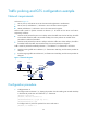
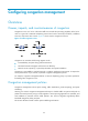
Traffic policing and GTS configuration example
Network requirements
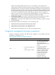
As shown in Figure 11:
• Server, Host A, and Host B can access the Internet through Router A and Router B.
• Server, Host A, and Ethernet 1/1 of Router A are in the same network segment.
• Host B and Ethernet 1/2 of Router A are in the same network segment.
Perform traffic control for packets received on Ethernet 1/1 of Router A from Server and Host A
respectively as follows:
• Limit the rate of packets from Server to 54 kbps. When the traffic rate is below 54 kbps, the traffic
is forwarded. When the traffic rate exceeds 54 kbps, the excess packets are marked with IP
precedence 0 and then forwarded.
• Limit the rate of packets from Host A to 8 kbps. When the traffic rate is below 8 kbps, the traffic is
forwarded. When the traffic rate exceeds 8 kbps, the excess packets are dropped.
Traffic control for packets forwarded by Ethernet 1/1 and Ethernet 1/2 of Router B is as follows:
• Limit the incoming traffic rate on Ethernet 1/1 of Router B to 500 kbps, and the excess packets are
dropped.
• Limit the outgoing traffic rate on Ethernet 1/2 of Router B to 1000 kbps, and the excess packets are
dropped.
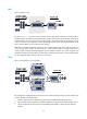
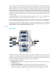
Figure 11 Network diagram
Configuration procedure
1. Configure Router A:
# Configure GTS on Ethernet 1/3, shaping the packets when the sending rate exceeds 500 kbps
to decrease the packet loss rate of Ethernet 1/1 of Router B.
<RouterA> system-view
[RouterA] interface ethernet 1/3
[RouterA-Ethernet1/3] qos gts any cir 500
[RouterA-Ethernet1/3] quit
# Configure ACLs to permit the packets from Server and Host A.
[RouterA] acl number 2001
Internet
1.1.1.1/8 1.1.1.2/8
Eth1/3
Eth1/1
Eth1/2
Eth1/2
Eth1/1
Host A
Host B
Router A
Router B
Server
Ethernet