HP MSR2000/3000/4000 Router Series Fundamentals Configuration Guide (V7) Part number: 5998-3986 Software version: CMW710-R0007P02 Document version: 6PW100-20130927
Legal and notice information © Copyright 2013 Hewlett-Packard Development Company, L.P. No part of this documentation may be reproduced or transmitted in any form or by any means without prior written consent of Hewlett-Packard Development Company, L.P. The information contained herein is subject to change without notice.
Contents Using the CLI ································································································································································ 1 CLI views ············································································································································································ 1 Entering system view from user view ·········································································································
RBAC configuration example for RADIUS authentication users ······································································· 28 RBAC configuration example for HWTACACS authentication users ······························································ 31 Troubleshooting RBAC ··················································································································································· 34 Local users have more access permissions than intended ························
Using the device as an FTP client ································································································································· 79 Establishing an FTP connection ···························································································································· 79 Managing directories on the FTP server ············································································································· 81 Working with files on the FTP serv
Enabling automatic configuration archiving····································································································· 102 Manually archiving the running configuration ································································································· 103 Rolling back configuration·································································································································· 103 Specifying a next-startup configuration file ···········
Banner types ························································································································································ 133 Banner input methods ········································································································································· 133 Configuration procedure ···································································································································· 134 Rebooting the devi
Using the CLI At the command-line interface (CLI), you can enter text commands to configure, manage, and monitor your device. Figure 1 CLI example You can use a variety of methods to log in to the CLI. For example, you can log in through the console port, or by using Telnet or SSH. For more information about login methods, see "Login overview." CLI views Commands are grouped in different views by function. To use a command, you must enter its view.
changed by using the sysname command. In user view, you can perform basic operations including display, debug, file management, FTP, Telnet, clock setting, and reboot. From user view, you can enter system view to configure global settings (such as the daylight saving time, banners, and hotkeys) and some functions. The system view prompt is [Device-name]. From system view, you can enter different function views.
backup Backup the startup configuration file to a TFTP server boot-loader Set boot loader … • Enter a space and a question mark after a command keyword to display all available, subsequent keywords and arguments. { If the question mark is in the place of a keyword, the CLI displays all possible keywords, each with a brief description.
Editing a command line To edit a command line, use the keys listed in Table 1 or the hotkeys listed in Table 2. When you are finished, you can press Enter to execute the command. Table 1 Command line editing keys Keys Function Common keys If the edit buffer is not full, pressing a common key inserts a character at the position of the cursor and moves the cursor to the right. The edit buffer can store up to 511 characters.
For example, if you configure show as the alias for the display keyword, you can enter either show clock or display clock to execute the display clock command. Usage guidelines After you successfully execute a command by using a keyword alias, the system saves the keyword, instead of its alias, to the running configuration. If a string you entered for a command partially matches an alias and a keyword, the command indicated by the alias is executed.
Step Command Remarks By default: • Ctrl+G is assigned the display current-configuration command. 2. Assign a command to a hotkey. hotkey { ctrl_g | ctrl_l | ctrl_o | ctrl_t | ctrl_u } command • Ctrl+L is assigned the display ip routing-table command. • Ctrl+O is assigned the undo debugging all command. • No command is assigned to Ctrl+T or Ctrl+U. 3. (Optional.) Display hotkeys. Available in any view.
Enabling redisplaying entered-but-not-submitted commands After you enable redisplaying entered-but-not-submitted commands, when your input is interrupted by system information output, the system redisplays your input after finishing the output so you can continue entering the command line. To enable redisplaying entered-but-not-submitted commands: Step 1. 2. Enter system view. Enable redisplaying entered-but-not-submit ted commands.
Table 4 Comparison between the two types of command history buffers Item Command history buffer for a user line Command history buffer for all user lines What kind of commands are stored in the buffer? Commands successfully executed by the current user of the user line. Commands successfully executed by all login users. Cleared when the user logs out? Yes. No. How to view buffered commands? Use the display history-command command. Use the display history-command all command.
By default, up to 24 lines can be displayed on a screen. You can change the maximum number of lines that can be displayed on a screen by using the screen-length screen-length command. For more information about this command, see Fundamentals Command Reference. You can also disable pausing between screens of output for the current session. Then, all output is displayed at one time and the screen is refreshed continuously until the final screen is displayed.
5: Subnet mask: 255.255.255.0 6: Description: For LAN Access 7: Name: VLAN 0999 8: Tagged ports: 9: Untagged ports: 10: Ethernet1/1 None Filtering the output from a display command You can use the | { begin | exclude | include } regular-expression option to filter the display command output: • begin—Displays the first line matching the specified regular expression and all subsequent lines. • exclude—Displays all lines not matching the specified regular expression.
Characters Meaning Examples [^] Matches a single character that is not in the brackets. "[^16A]" matches a string that contains at least one character other than 1, 6, or A, such as "abc". A match can also contain 1, 6, or A (such as "m16"), but it cannot contain these three characters only (such as 1, 16, or 16A). {n} Matches the preceding character n times. The number n must be a nonnegative integer. "o{2}" matches "food", but not "Bob". {n,} Matches the preceding character n times or more.
line con 0 user-role network-admin # line vty 0 63 authentication-mode scheme user-role network-operator # ssh server enable # return # Use | exclude Direct in the display ip routing-table command to filter out direct routes and display only the non-direct routes. display ip routing-table | exclude Direct Destinations : 12 Routes : 12 Destination/Mask Proto Pre Cost NextHop Interface 2.2.2.0/24 OSPF 10 2 1.1.2.
# Verify whether the VLAN 1 settings are saved to file vlan.txt. more vlan.txt VLAN ID: 1 VLAN type: Static Route interface: Not configured Description: VLAN 0001 Name: VLAN 0001 Tagged ports: None Untagged ports: Ethernet1/2 # Append the VLAN 999 settings to the end of file vlan.txt. display vlan 999 >> vlan.txt # Verify whether the VLAN 999 settings are appended to the end of file vlan.txt. more vlan.
Task Command View and manage the output from a display command effectively. display command [ | [ by-linenum ] { begin | exclude | include } regular-expression ] [ > filename | >> filename ] For example: # Save the running configuration to a separate file named test.txt, with each line numbered. display current-configuration | by-linenum > test.txt # Append lines including "snmp" in the running configuration to the file test.txt. display current-configuration | include snmp >> test.
15
Configuring RBAC Role based access control (RBAC) controls user access to commands and resources based on user role. This chapter describes the basic idea of RBAC and guides you through the RBAC configuration procedure. Overview On devices that support multiple users, RBAC is used to assign command and resource access permissions to user roles that are created for different job functions. Users are given permission to access a set of commands and resources based on their user roles.
• XML element rule—Controls access to XML elements used for configuring the device. A user role can have multiple rules uniquely identified by rule numbers. The set of permitted commands in these rules are accessible to the user role. If two rules conflict, the one with higher number takes effect. For example, if rule 1 permits the ping command, rule 2 permits the tracert command, and rule 3 denies the ping command, the user role can use the tracert command but not the ping command.
User role name Permissions • level-0—Has access to diagnostic commands, including ping, tracert, ssh2, telnet, and super. Level-0 access rights are configurable. • level-1—Has access to the display commands (except display history-command all) of all features and resources in the system, in addition to all access rights of the user role level-0. Level-1 access rights are configurable. • level-2 to level-8, and level-10 to level-14—Have no access rights by default. Access rights are configurable.
{ If the user passes remote authorization, the remote AAA server assigns the user roles specified on the server. The AAA server can be a RADIUS or HWTACACS server. None-AAA authorization—If the user uses password authentication or no authentication, the device assigns user roles specified on the user line. This method also applies to SSH clients that use publickey or password-publickey authentication.
Step 3. (Optional.) Configure a description for the user role. Command Remarks description text By default, a user role has no description. Configuring user role rules Configure command, feature, and feature group rules to permit or deny the access of a user role to specific commands. You can configure up to 256 rules for a user role, but the total number of user role rules in the system cannot exceed 1024. If two rules of a user role conflict, the one with a higher rule number has priority.
Step 1. 2. Enter system view. Create a feature group and enter feature group view. Command Remarks system-view N/A role feature-group name feature-group-name By default, the system has the following predefined feature groups: • L2—Includes all Layer 2 commands. • L3—Includes all Layer 3 commands. These two groups are not user configurable. By default, a feature group has no features. 3. Add a feature to the feature group.
Step 3. 4. Command Enter user role VLAN policy view. (Optional.) Specify a list of VLANs accessible to the user role. Remarks vlan policy deny permit vlan vlan-id-list By default, the VLAN policies of user roles permit access to all VLANs. This command disables the access of the user role to any VLAN. By default, no accessible VLANs are configured. To add more accessible VLANs, repeat this step. Changing the VPN instance policy of a user role Step Command Remarks 1. Enter system view.
Step Command Remarks 1. Enter system view. system-view N/A 2. Enable the default user role function. role default-role enable The default user role function is disabled. Assigning user roles to remote AAA authentication users For remote AAA authentication users, user roles are configured on the remote authentication server. For information about configuring user roles for RADIUS users, see the RADIUS server documentation.
Assigning user roles to non-AAA authentication users on user lines Specify user roles for the following two types of login users on the user lines: • Users that use password authentication or no authentication. • SSH clients that use publickey or password-publickey authentication. User roles assigned to these SSH clients are specified in their respective local management user accounts. For more information about user lines, see "Login overview" and "Logging in to the CLI.
{ { If HWTACACS authentication is used, use a user account that has the target user role level or a user role level higher than the target user role. For example, if the user account test has the user role level-3, you can use this user account to obtain the level-0, level-1, level-2, or level-3 user role. By using this method, you must enter the correct username and password to pass authentication.
Step Set a local authentication password for a user role. 3. Command Remarks • In non-FIPS mode: Use this step for local password authentication. super password [ role rolename ] [ { hash | simple } password ] • In FIPS mode: super password [ role rolename ] By default, no password is configured. If you do not specify the role rolename option, the command sets the password for network-admin.
• Accesses none of the interfaces except Ethernet 1/2 to Ethernet 1/4. Figure 3 Network diagram Configuration procedure # Assign an IP address to Ethernet 1/1, the interface connected to the Telnet user. system-view [Router] interface ethernet 1/1 [Router-Ethernet1/1] ip address 192.168.1.70 255.255.255.0 [Router-Ethernet1/1] quit # Enable Telnet server. [Router] telnet server enable # Enable scheme authentication on the user lines for Telnet users.
# To make sure the user has only the permissions of role1, remove the user from the default user role network-operator. [Router-luser-manage-user1] undo authorization-attribute user-role network-operator [Router-luser-manage-user1] quit Verifying the configuration # Telnet to the router, and enter the username and password to access the router. (Details not shown.) # Verify that you cannot enter any interface view except the views of Ethernet 1/2 to Ethernet 1/4. This example uses Ethernet 1/1.
Figure 4 Network diagram Configuration procedure Make sure the settings on the router and the RADIUS server match. 1. Configure the router: # Assign an IP address to Ethernet 1/1, the interface connected to the Telnet user. system-view [Router] interface ethernet 1/1 [Router-Ethernet1/1] ip address 192.168.1.70 255.255.255.0 [Router-Ethernet1/1] quit # Assign an IP address to Ethernet1/2, the interface connected to the FreeRADIUS server.
[Router-isp-bbb] authorization login radius-scheme rad [Router-isp-bbb] quit # Create the feature group fgroup1. [Router] role feature-group name fgroup1 # Add the features arp and radius to the feature group. [Router-featuregrp-fgroup1] feature arp [Router-featuregrp-fgroup1] feature radius [Router-featuregrp-fgroup1] quit # Create the user role role2. [Router] role name role2 # Configure rule 1 to allow the user role to use all commands available in ISP view.
[Router-isp-abc] authentication login radius-scheme abc [Router-isp-abc] quit # Verify that you can use all read and write commands of the features radius and arp. This example uses radius. [Router] radius scheme rad [Router-radius-rad] primary authentication 2.2.2.2 [Router-radius-rad] display radius scheme rad … Output of the RADIUS scheme is omitted. # Verify that you cannot configure any VLAN except VLANs 1 to 20. This example uses VLAN 10 and VLAN 30.
Configuration procedure 1. Configure the router: # Assign an IP address to VLAN-interface 2, the interface connected to the Telnet user. system-view [Router] interface vlan-interface 2 [Router-Vlan-interface2] ip address 192.168.1.70 255.255.255.0 [Router-Vlan-interface2] quit # Assign an IP address to VLAN-interface 3, the interface connected to the HWTACACS server. [Router] interface vlan-interface 3 [Router-Vlan-interface3] ip address 10.1.1.2 255.255.255.
# Delete the defualt user role network-operator. [Router-luser-manage-test] undo authorization-attribute user-role network-operator [Router-luser-manage-test] quit # Set the password to 654321 for the user role level-3. [Router] super password role level-3 simple 654321 [Router] quit 2. Configure the HWTACACS server: This example uses ACSv4.0. a. Add a user account test. b. Access the Advanced TACACS+ Settings page. c. Select Level 3 for the Max Privilege for any AAA Client option. d.
Press CTRL+K to abort Connected to 192.168.1.59 ... ****************************************************************************** * Copyright (c) 2004-2013 Hewlett-Packard Development Company, L.P. * * Without the owner's prior written consent, * * no decompiling or reverse-engineering shall be allowed.
Local users have more access permissions than intended Symptom A local user can use more commands than should be permitted by the assigned user roles. Analysis The local user might have been assigned to user roles without your knowledge. For example, the local user is automatically assigned a default user role when you create it. Solution Use the display local-user command to examine the local user accounts for undesirable user roles, and delete them.
Login overview The first time you access the device, you can only log in to the CLI through the console port. After login, you can change console login parameters, or configure other access methods, including AUX, Telnet, SSH, modem, and SNMP. The device supports the FIPS mode that complies with NIST FIPS 140-2 requirements. Support for features, commands, and parameters might differ in FIPS mode and non-FIPS mode. For more information about FIPS mode, see Security Configuration Guide.
Login method Default settings and minimum configuration requirements By default, modem dial-in is enabled and requires a password, but no password is configured. • Logging in through a pair of modems To log in through modems, complete the following configuration tasks: • Configure a password for password authentication, or change the authentication mode and configure parameters for the new authentication mode. • Assign a user role to AUX login users (network-operator by default).
Logging in through the console port for the first device access The first time you access the device, you can only log in to the CLI through the console port. To log in through the console port, prepare a console terminal (for example, a PC) and make sure the console terminal has a terminal emulation program, for example, HyperTerminal in Windows XP. To log in through the console port: 1. Connect the DB-9 female connector of the console cable to the serial port of the PC. 2.
Figure 8 Creating a connection Figure 9 Specifying the serial port used to establish the connection 39
Figure 10 Setting the properties of the serial port 5. Power on the device and press Enter as prompted. Figure 11 Device CLI 6. At the default user view prompt , enter commands to configure the device or view the running status of the device. To get help, enter ?.
Logging in to the CLI By default, you can log in to the CLI only through the console port. After you log in, you can configure other login methods, including Telnet, SSH, AUX, and modem dial-in. To prevent illegal access to the CLI and control user behavior, you can configure login authentication, assign user roles, configure command authorization and command accounting, and use ACLs to filter unauthorized logins.
An absolute number uniquely identifies a user line among all user lines. The user lines are numbered starting from 0 and incrementing by 1 and in the sequence of console, TTY, AUX, and VTY lines. You can use the display line command without any parameters to view supported user lines and their absolute numbers. A relative number uniquely identifies a user line among all user lines that are the same type. The number format is user line type + number.
FIPS compliance The device supports the FIPS mode that complies with NIST FIPS 140-2 requirements. Support for features, commands, and parameters might differ in FIPS mode and non-FIPS mode. For more information about FIPS mode, see Security Configuration Guide. In FIPS mode, the device supports only the scheme login authentication mode, and does not support Telnet.
Disabling authentication for console/AUX login Step 1. Enter system view. Command Remarks system-view N/A Use either command. • To enter console/AUX line view: 2. 3. 4. Enter console/AUX line view or class view. Disable authentication. Assign a user role.
Figure 15 Accessing the CLI through the AUX port without authentication Configuring password authentication for console/AUX login Step 1. Enter system view. Command Remarks system-view N/A Use either command. • To enter console/AUX line view: 2. Enter console/AUX line view or class view.
The next time you attempt to log in through the console/AUX port, you must provide the configured login password, as shown in Figure 16 and Figure 17. Figure 16 Password authentication interface for console login Figure 17 Password authentication interface for AUX login Configuring scheme authentication for console/AUX login Step 1. Enter system view.
Step Command Remarks Use either command. • To enter console/AUX line 2. Enter console/AUX line view or class view. view: line { aux | console } first-number [ last-number ] • To enter console/AUX line class view: line class { aux | console } 3. Enable scheme authentication. authentication-mode scheme Settings configured in a user line class view are applied as user-defined default settings to all user lines of the line class.
Figure 19 Scheme authentication interface for AUX login Configuring common console/AUX line settings Some common settings configured for a console or AUX line take effect immediately and can interrupt the current session. Use a login method different from console/AUX login to log in to the device before you change console/AUX line settings.
Step Command Remarks The default is 1. 5. Specify the number of stop bits. stopbits { 1 | 1.5 | 2 } Stop bits indicate the end of a character. The more the stop bits, the slower the transmission. This command is not available in console/AUX line class view. The default is 8. 6. Specify the number of data bits for each character. databits { 5 | 6 | 7 | 8 } The setting depends on the character coding type.
Step Command Remarks The default is 10 minutes. 13. Set the session idle timeout. idle-timeout minutes [ seconds ] If there is no interaction between the device and the user within the idle timeout, the system automatically terminates the user connection on the user line. If you set the idle timeout to 0, the session will not be aged out. By default, no command is specified for a user line to be automatically executed. 14.
Task Remarks (Optional.) Setting the maximum number of concurrent Telnet users N/A (Optional.) Setting the DSCP value for outgoing Telnet packets N/A (Optional.) Configuring common VTY line settings N/A The Telnet login configuration is effective only for users who log in after the configuration is completed. Disabling authentication for Telnet login Step Command Remarks 1. Enter system view. system-view N/A 2. Enable Telnet server.
Figure 20 Telnetting to the device without authentication Configuring password authentication for Telnet login Step Command Remarks 1. Enter system view. system-view N/A 2. Enable Telnet server. telnet server enable By default, the Telnet server function is disabled. Use either command. • To enter VTY line view: 3. Enter VTY line view or class view.
Step 6. (Optional.) Assign a user role. Command Remarks user-role role-name By default, a VTY line user is assigned the user role network-operator. The next time you attempt to Telnet to the device, you must provide the configured login password, as shown in Figure 21. If the maximum number of login users has been reached, your login attempt fails and the message "All user lines are used, please try later!" appears.
Step 4. Enable scheme authentication. Command Remarks authentication-mode scheme By default, password authentication is enabled for VTY lines. To use scheme authentication, you must also configure login authentication methods in ISP domain view. For more information, see Security Configuration Guide. The next time you attempt to Telnet to the CLI, you must provide the configured login username and password, as shown in Figure 22.
Step 1. Enter system view. 2. Set the DSCP value for outgoing Telnet packets. Command Remarks system-view N/A • For a Telnet server running IPv4: telnet server dscp dscp-value • For a Telnet server running IPv6: By default, the DSCP value is 48. telnet server ipv6 dscp dscp-value Configuring common VTY line settings For a VTY line, you can specify a command that is to be automatically executed when a user logs in.
Step 8. Set the size of command history buffer. Command Remarks history-command max-size value By default, the buffer saves 10 history commands. By default, the session idle timeout is 10 minutes for all user lines. 9. Set the session idle timeout. idle-timeout minutes [ seconds ] If there is no interaction between the device and the user within the idle timeout, the system automatically terminates the user connection on the user line.
Step Command Remarks • Log in to an IPv4 Telnet server: 4. Use the device to log in to a Telnet server. telnet remote-host [ service-port ] [ vpn-instance vpn-instance-name ] [ source { interface interface-type interface-number | ip ip-address } ] [ dscp dscp-value ] • Log in to an IPv6 Telnet server: Use either command.
Step Command Remarks • In non-FIPS mode: 4. Create an SSH user and specify the authentication mode. ssh user username service-type stelnet authentication-type { password | { any | password-publickey | publickey } assign publickey keyname } • In FIPS mode: By default, no SSH user is configured on the device. ssh user username service-type stelnet authentication-type { password | password-publickey assign publickey keyname } Use either command. • To enter VTY line view: 5.
Using the device to log in to an SSH server You can use the device as an SSH client to log in to an SSH server. If the server is located in a different subnet than the device, make sure the two devices have routes to reach each other. Figure 24 Logging in to an SSH client from the device Perform the following tasks in user view: Task Command Log in to an IPv4 SSH server. ssh2 server Log in to an IPv6 SSH server. ssh2 ipv6 server To work with the SSH server, you might need to configure the SSH client.
{ ATS0=1—Configures auto-answer on first ring. { AT&D—Ignores DTR signals. { AT&K0—Disables local flow control. { AT&R1—Ignores RTS signals. { AT&S0—Forces DSR to remain on. { ATEQ1&W—Disables the modem from returning command responses and execution results, and saves configuration. To verify your configuration, enter AT&V to display the configuration results. NOTE: The configuration commands and output vary by modem. For more information, see the modem user guide. 5.
Figure 28 Configuring the dialing parameters 7. Dial the telephone number to establish a connection to the device. Figure 29 Dialing the number 8. After you hear the dial tone, press Enter as prompted. If the authentication mode is none, the prompt appears. If the authentication mode is password or scheme, you must enter the correct authentication information as prompted.
IMPORTANT: Do not directly close the HyperTerminal. Doing so can cause some modems to stay in use, and your subsequent dial-in attempts will always fail. To disconnect the PC from the device, execute the appropriate ATH command in the HyperTerminal. If the command cannot be entered, type AT+ + + and press Enter, and when the word OK appears, execute the ATH command. The connection is terminated if OK is displayed. You can also terminate the connection by clicking in the HyperTerminal window.
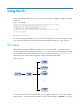
Accessing the device through SNMP You can run SNMP on an NMS to access the device MIB and perform Get and Set operations to manage and monitor the device. Figure 31 SNMP access diagram Get/Set requests NMS Get/Set responses and Traps MIB Agent The device supports SNMPv1, SNMPv2c, and SNMPv3, and can work with various network management software products, including IMC. However, the device and the NMS must use the same SNMP version.
Step 5. Create an SNMPv3 user. Command Remarks snmp-agent usm-user v3 user-name group-name [ remote { ip-address | ipv6 ipv6-address } [ vpn-instance vpn-instance-name ] ] [ { cipher | simple } authentication-mode { md5 | sha } auth-password [ privacy-mode { aes128 | des56 } priv-password ] ] [ acl acl-number | acl ipv6 ipv6-acl-number ] * To send informs to an SNMPv3 NMS, you must use the remote ip-address option to specify the IP address of the NMS.
Controlling user access Use ACLs to prevent unauthorized access and configure command authorization and accounting to monitor and control user behavior. For more information about ACLs, see ACL and QoS Configuration Guide. Controlling Telnet/SSH logins Use basic ACLs (2000 to 2999) to filter Telnet and SSH logins by source IP address. Use advanced ACLs (3000 to 3999) to filter Telnet and SSH logins by source and/or destination IP address.
Figure 32 Network diagram Configuration procedure # Configure an ACL to permit packets sourced from Host A and Host B. system-view [Sysname] acl number 2000 match-order config [Sysname-acl-basic-2000] rule 1 permit source 10.110.100.52 0 [Sysname-acl-basic-2000] rule 2 permit source 10.110.100.46 0 [Sysname-acl-basic-2000] quit # Apply the ACL to filter Telnet logins.
Step Command Remarks • SNMP community: snmp-agent community { read | write } community-name [ mib-view view-name ] [ acl acl-number | acl ipv6 ipv6-acl-number ] * • SNMPv1/v2c group: snmp-agent group { v1 | v2c } group-name [ read-view view-name ] [ write-view view-name ] [ notify-view view-name ] [ acl acl-number | acl ipv6 ipv6-acl-number ] * • SNMPv3 group: 2. Apply the ACL to an SNMP community, group, or user.
[Sysname-acl-basic-2000] rule 2 permit source 10.110.100.46 0 [Sysname-acl-basic-2000] quit # Associate the ACL with the SNMP community and the SNMP group. [Sysname] snmp-agent community read aaa acl 2000 [Sysname] snmp-agent group v2c groupa acl 2000 [Sysname] snmp-agent usm-user v2c usera groupa acl 2000 Configuring command authorization By default, commands are available for a user depending only on that user's user roles.
Step 4. Enable command authorization. Command Remarks command authorization By default, command authorization is disabled, and the commands available for a user only depend on the user role. Configuration example Network requirements Configure the device in Figure 34 so a user can use Host A to log in to the device and execute only commands that are authorized by the HWTACACS server or, when the HWTACACS server is not available, the device itself.
# For the system-predefined domain system, configure the authentication method for login users and the command authorization method to use the HWTACACS scheme and, if the HWTACACS server is unavailable, use local authentication and local authorization as the backup.
Step Command Remarks Use either command. • To enter user line view: 2. line { first-number1 [ last-number1 ] | { aux | console | tty | vty } first-number2 [ last-number2 ] } Enter user line view or user line class view. • To enter user line class view: line class { aux | console | tty | vty } 3. 4. Enable scheme authentication. Enable command accounting.
Figure 35 Network diagram Configuration procedure # Enable the Telnet server. system-view [Device] telnet server enable # Enable command accounting for user line Console 0. [Device] line console 0 [Device-line-console0] command accounting [Device-line-console0] quit # Enable command accounting for user lines VTY 0 through VTY 4. [Device] line vty 0 63 [Device-line-vty0-63] command accounting [Device-line-vty0-63] quit # Configure an HWTACACS scheme that uses the HWTACACS server at 192.168.2.
[Device-isp-system] accounting login hwtacacs-scheme tac [Device-isp-system] authorization login none [Device-isp-system] quit 73
Configuring FTP File Transfer Protocol (FTP) is an application layer protocol based on the client/server model. It is used to transfer files from one host to another over an IP network. FTP server uses TCP port 20 to transfer data and TCP port 21 to transfer control commands. For more information about FTP, see RFC 959. FTP supports the following transfer modes: • Binary mode—Used to transfer image files, such as .app, .bin, and .btm files. • ASCII mode—Used to transfer text files, such as .txt, .
Step Command Remarks 2. Enable the FTP server. ftp server enable By default, the FTP server is disabled. 3. (Optional.) Use an ACL to control access to the FTP server. ftp server acl { acl-number | ipv6 acl-number6 } By default, no ACL is used for access control. The default idle-timeout interval is 30 minutes. 4. (Optional.) Configure the idle-timeout interval.
Manually releasing FTP connections Task Command • Release the FTP connection established using a specific user Manually release FTP connections. account: free ftp user username • Release the FTP connection to a specific IP address: free ftp user-ip [ ipv6 ] client-address [ port port-num ] Displaying and maintaining the FTP server Execute display commands in any view. Task Command Display FTP server configuration and status information.
[Sysname-luser-abc] quit # Enable the FTP server. [Sysname] ftp server enable [Sysname] quit # Examine the storage space for space insufficiency and delete unused files for more free space. dir Directory of cfa0: 0 -rw- 0 Sep 27 2010 14:43:34 kernel.bin 1 -rw- 0 Sep 27 2010 14:43:34 base.bin 2 drw- - Jun 29 2011 18:30:38 logfile 3 drw- - Jun 21 2011 14:51:38 diagfile 4 drw- - Jun 21 2011 14:51:38 seclog 5 -rw- 2943 Jul 02 2011 08:03:08 startup.
FTP server, and download the configuration file startup.cfg from the FTP server to the FTP client for backup. Figure 38 Network diagram Configuration procedure 1. Configure IP addresses as shown in Figure 38, and make sure the device and PC can reach other. (Details not shown.) 2.
220 FTP service ready. User(1.1.1.1:(none)):abc 331 Password required for abc. Password: 230 User logged in. # Use the ASCII mode to download the configuration file startup.cfg from the device to the PC for backup. ftp> ascii 200 TYPE is now ASCII ftp> get startup.cfg back-startup.cfg # Use the binary mode to upload the file temp.bin from the PC to the CF card root directory of the active MPU. ftp> binary 200 TYPE is now 8-bit binary ftp> put temp.bin # Exit FTP.
Step Command Remarks • (Method 1) Log in to the FTP server 4. directly in user view: ftp [ server-address [ service-port ] [ vpn-instance vpn-instance-name ] [ dscp dscp-value | source { interface interface-type interface-number | ip source-ip-address } ] ] * Log in to the FTP server. • (Method 2) Log in to the FTP server in FTP client view: a. ftp Use either method. The source IP address specified in the ftp command takes precedence over the one set by the ftp client source command. b.
Managing directories on the FTP server Task Command • Display the detailed information of a directory or file Display directory and file information on the FTP server. on the FTP server: dir [ remotefile [ localfile ] ] • Display the name of a directory or file on the FTP server: ls [ remotefile [ localfile ] ] Change the working directory on the FTP server. cd { directory | .. | / } Return to the upper level directory on the FTP server. cdup Display the working directory that is being accessed.
Task Command Remarks Set the file transfer mode to binary. binary The default file transfer mode is ASCII. Set the FTP operation mode to passive. passive The default mode is passive. Display or change the local working directory of the FTP client. lcd [ directory | / ] N/A Upload a file to the FTP server. put localfile [ remotefile ] N/A Download a file from the FTP server. get remotefile [ localfile ] N/A Add the content of a file on the FTP client to a file on the FTP server.
Task Command Remarks Display FTP connection status. status N/A Display the system information of the FTP server. system N/A Enable or disable FTP operation information display. verbose By default, this function is enabled. Enable or disable FTP client debugging. debug By default, FTP client debugging is disabled. Clear the reply information in the buffer.
FTP client configuration example for MSR2000/MSR3000 Network requirements • Use the device as the FTP client and the PC as the FTP server. • Log in to the FTP server from the FTP client using the user account with username abc and password 123456 (which has been created on the PC). • Download the file temp.bin from the PC to the device, and upload the configuration file startup.cfg from the device to the PC for backup.
200 TYPE is now ASCII ftp> put startup.cfg back-startup.cfg local: startup.cfg remote: back-startup.cfg 150 Connecting to port 47461 226 File successfully transferred 3494 bytes sent in 5.646 seconds (618.00 kbyte/s) ftp> bye 221-Goodbye. You uploaded 2 and downloaded 2 kbytes. 221 Logout. FTP client configuration example for MSR4000 Network requirements • Use the device as the FTP client and the PC as the FTP server.
# Download the file temp.bin from the PC to the CF card root directory of the active MPU. ftp> get temp.bin local: temp.bin remote: temp.bin 150 Connecting to port 47457 226 File successfully transferred 23951480 bytes received in 95.399 seconds (251.0 kbyte/s) # Download the file temp.bin from the PC to the CF card root directory of the standby MPU (in slot 1). ftp> get temp.bin slot1#cfa0:/temp.bin # Set the file transfer mode to ASCII and upload the configuration file startup.
Configuring TFTP Trivial File Transfer Protocol (TFTP) is a simplified version of FTP for file transfer over secure reliable networks. TFTP uses UDP port 69 for data transmission. In contrast to TCP-based FTP, TFTP does not require authentication or complex message exchanges, and is easier to deploy. TFTP is suited for reliable network environments. The device can only operate as a TFTP client. You can upload a file from the device to the TFTP server or download a file from the TFTP server to the device.
Step 5. Command Download or upload a file in an IPv4 network. Remarks tftp server-address { get | put | sget } source-filename [ destination-filename ] [ vpn-instance vpn-instance-name ] [ dscp dscp-value | source { interface interface-type interface-number | ip source-ip-address } ] * The source IP address specified in this command takes precedence over the one set by the tftp client source command. Use this command in user view.
Managing the file system This chapter describes how to manage the device's file system, including the storage media, directories, and files. IMPORTANT: • Before managing storage media, files, and directories, make sure you know the possible impacts. • A file or directory whose name starts with a period (.) is considered a hidden file or directory. Do not give a common file or directory a name that starts with a period. • Some system files and directories are hidden.
Format [path/]file-name Description Example Specifies a file in a specific folder in the current working directory. • test/a.cfg indicates a file named a.cfg The path argument represents the path to the file. If the file is in a single-level folder, specify the folder name for the argument. If the file is in a nested folder, separate each folder name by a forward slash (/). in the test folder in the current working directory. • test/subtest/a.cfg indicates a file named a.
FIPS compliance The device supports the FIPS mode that complies with NIST FIPS 140-2 requirements. Support for features, commands, and parameters might differ in FIPS mode and non-FIPS mode. For more information about FIPS mode, see Security Configuration Guide. Managing files CAUTION: To avoid file system corruption: • On an MSR2000 or MSR3000, do not install or remove a storage medium during file operations.
Copying a file Perform this task in user view. Task Command • In non-FIPS mode: Copy a file. copy fileurl-source fileurl-dest [ vpn-instance vpn-instance-name ] [ source interface interface-type interface-number ] • In FIPS mode: copy fileurl-source fileurl-dest Moving a file Perform this task in user view. Task Command Move a file. move fileurl-source fileurl-dest Compressing/decompressing a file Perform the following tasks in user view: Task Command Compress a file.
Deleting files from the recycle bin Perform the following task in user view: Task Command Delete files from the recycle bin. reset recycle-bin [ /force ] Calculating the digest of a file File digests can be used to verify file integrity. For example, you can calculate a software image file's digest and compare it with the digest on the HP website. Perform this task in user view. Task Command Calculate the digest of a file.
Changing the current working directory Perform this task in user view. Task Command Change the current working directory. cd { directory | .. | / } Creating a directory Perform this task in user view. Task Command Create a directory. mkdir directory Removing a directory To remove a directory, you must delete all files and subdirectories in this directory. To delete a file, use the delete command. To delete a subdirectory, use the rmdir command.
Repairing a storage medium If part of a storage medium is inaccessible, use the fixdisk command to examine and repair the medium. Before repairing a storage medium, make sure no other users are accessing the medium. Otherwise, the repair operation fails. Perform this task in user view. Task Command Repair a storage medium. fixdisk medium-name Formatting a storage medium CAUTION: After a storage medium is formatted, all files and directories on it are erased and cannot be restored.
Task Command Remarks Unmount a storage medium. umount medium-name By default, a storage medium is automatically mounted and in mounted state when connected to the system. Setting the operation mode for files and folders The device supports the following file and folder operation modes: • alert—The system prompts for confirmation when your operation might cause problems such as file corruption and data loss. This mode provides an opportunity to cancel a disruptive operation.
Managing configuration files You can use the CLI or the Boot menu to manage configuration files. This chapter explains how to manage configuration files from the CLI. Overview A configuration file saves a set of commands for configuring software features on the device. You can save any configuration to a configuration file so they can survive a reboot. You can also back up configuration files to a host for future use.
Next-startup configuration file redundancy You can specify one main next-startup configuration file and one backup next-startup configuration file for redundancy. At startup, the device tries to start up with the main configuration file. If the main configuration file is corrupted or unavailable, the device tries the backup configuration file. If the backup configuration file is corrupted or unavailable, the device starts up with the factory defaults.
authorization-attribute user-role network-admin # interface Ethernet1/1 port link-mode route ip address 1.1.1.1 255.255.255.0 # FIPS compliance The device supports the FIPS mode that complies with NIST FIPS 140-2 requirements. Support for features, commands, and parameters might differ in FIPS mode and non-FIPS mode. For more information about FIPS mode, see Security Configuration Guide.
Use the safe mode if the power source is not reliable or you are remotely configuring the device. To save the running configuration on an MSR2000 or MSR3000, perform either of the following tasks in any view: Task Command Remarks Save the running configuration to a configuration file without specifying the file as a next-startup configuration file. save file-url N/A For reliable configuration saving, HP recommends that you specify the safely keyword.
Configuring configuration rollback To replace the running configuration with the configuration in a configuration file without rebooting the device, use the configuration rollback function. This function helps you revert to a previous configuration state or adapt the running configuration to different network environments.
Configuration procedure To configure configuration archive parameters: Step Enter system view. 1. Command Remarks system-view N/A Do not include MPU slot information in the directory name. By default, no path or file name prefix is set for configuration archives, and the system does not regularly save configuration. Configure the directory and file name prefix for archiving the running configuration. 2. (Optional.) Set the maximum number of configuration archives. 3.
Step Command Enable automatic configuration archiving and set the archiving interval. 2. Remarks By default, this function is disabled. To view configuration archive names and their archiving time, use the display archive configuration command. archive configuration interval minutes Manually archiving the running configuration To save system resources, disable automatic configuration archiving and manually archive the configuration if the configuration will not be changed very often.
is undo A C, the configuration rollback function cannot undo the A B C command, because the system does not recognize the undo A B C command. • A command (for example, a hardware-dependent command) cannot be deleted, overwritten, or undone due to system restrictions. • The commands in different views are dependent on each other. • Commands or command settings that the device does not support cannot be added to the running configuration. Specifying a next-startup configuration file You can specify a .
Step 1. 2. Command Remarks (Optional.) Verify that a next-startup configuration file has been specified in user view. display startup If no next-startup configuration file has been specified, the backup operation will fail. Back up the next-startup configuration file to a TFTP server in user view. backup startup-configuration to dest-addr [dest-filename ] This command is not supported in FIPS mode.
To delete a file that is set as both main and backup next-startup configuration files, you must execute both the reset saved-configuration backup command and the reset saved-configuration main command. Using only one of the commands removes the specific file attribute instead of deleting the file. For example, if the reset saved-configuration backup command is executed, the backup next-startup configuration file setting is set to NULL, but the file is still used as the main file.
107
Upgrading software This chapter describes types of software and how to upgrade software from the CLI. For a comparison of all software upgrade methods, see "Upgrade methods." Overview Software upgrade enables you to have new features and fix bugs. Before performing an upgrade, use the release notes for the new software version to verify software and hardware compatibility and evaluate upgrade impacts. Software types The following software types are available: • Boot ROM image—A .
This procedure assumes that the main image set and the backup image set have feature packages and patch packages. If an image set does not have feature packages or patch packages, the system can use the image set to start up after the boot and system images pass verification. If both of the main and backup boot images are invalid or unavailable, connect to the console port and power cycle the device to access the Boot menu for loading a boot image.
Figure 43 System startup process Select the Reboot option to reboot the device Start Boot ROM runs Press Ctrl+B promptly? Enter Boot menu to upgrade Boot ROM or startup software images Yes No Startup software images run System starts up and CLI appears Finish Upgrade methods Upgrading method Software types Upgrading from the CLI • Boot ROM image • Comware images (excluding patches) Upgrading from the Boot menu • Boot ROM image • Comware software images Remarks This method is disruptive.
If you skip this task, the device automatically upgrades the Boot ROM when upgrading the startup software images. The Boot ROM image preloaded into the Boot ROM does not affect the device running status. 4. Specify the image file as the startup software image file. 5. Reboot the device. 6. Verify the upgrade. Preparing for the upgrade 1. Use the display version command to verify the current Boot ROM image version and startup software version. 2.
Step Command Remarks By default, this function is enabled. 2. (Optional.) Enable Boot ROM image validity check. bootrom-update security-check enable 3. Return to user view. quit 4. Load the upgrade Boot ROM image to the Normal area of Boot ROM. This function examines the image for wrong file type, file corruption, and hardware incompatibility. HP recommends enabling it to avoid an upgrade failure.
Step Command Remarks You can also specify a backup startup image file. • Method 1: 1. Specify the upgrade file as the main startup image file. boot-loader file ipe-filename { backup | main } • Method 2: boot-loader file boot boot-package system system-package [ feature feature-package&<1-30> ] { backup | main } Upgrade files must be saved in the root directory of the storage medium.
Step Command Remarks • Method 1: When you use method 3, make sure you understand the following requirements and upgrade results: • Method 2: • If the active MPU started up with main boot-loader file ipe-filename slot slot-number { backup | main } 2. Specify main or backup startup images for the standby MPU.
IMPORTANT: To ensure a successful synchronization in a multi-user environment, prevent users from rebooting or swapping MPUs during the software synchronization process. You can configure the information center to output the synchronization status to configuration terminals (see Network Management and Monitoring Configuration Guide). To enable software synchronization from the active MPU to the standby MPU at startup: Step Command Remarks 1. Enter system view. system-view N/A 2.
Configuration procedure # Configure IP addresses and routes to make sure the device and the TFTP server can reach each other. (Details not shown.) # Complete TFTP settings on both the device and the TFTP server. (Details not shown.) # Display information about the current software images. display version # Use TFTP to download the image file startup-a2105.ipe from the TFTP server to the root directory of the storage medium. tftp 2.2.2.2 get startup-a2105.ipe # (Optional.
# Complete TFTP settings on both the device and the TFTP server. (Details not shown.) # Display information about the current software images. display version # Use TFTP to download the image file startup-a2105.ipe from the TFTP server to the root directory of the storage medium on the active MPU. tftp 2.2.2.2 get startup-a2105.ipe # (Optional.) Back up the image file to startup-a2105-backup.ipe. Skip this step if the storage medium does not have sufficient space.
Using the emergency shell At startup, the device tries to locate and load the Comware startup software images, which might include a boot image, a system image, some feature images, and some patch images. If the boot image exists and can be used but the system image or any feature or patch image is missing or corrupted, the device enters emergency shell mode. After the device enters emergency shell mode, you can log in through the console port and get and load a system image to start the Comware system.
Task Command Remarks Display the contents of a file. more file-url N/A Permanently delete a file. delete file-url N/A Delete a folder. rmdir directory To delete a folder, first delete all files and child folders in the folder. Format a storage medium. format storage-medium N/A Obtaining a system image from an FTP/TFTP server If the required system image is saved on an FTP or TFTP server, configure the management Ethernet port and obtain the system image as described in the following sections.
Step Command Remarks 2. Enter management Ethernet port view. interface m-eth0 N/A 3. Assign an IPv6 address to the port. ipv6 address ipv6-address prefix-length By default, the management Ethernet port has no IPv6 address. 4. Specify an IPv6 gateway for the port. ipv6 gateway ipv6-address By default, the management Ethernet port has no IPv6 gateway configured. 5. Bring up the port. undo shutdown By default, the management Ethernet port is up. 6. Return to system view.
Task Command Telnet to an IPv4 server. telnet server-ipv4-address Use SSH to connect to an IPv4 server. ssh2 server-ipv4-address Use FTP to download a file from or upload a file to an IPv4 server. ftp server-ipv4-address user username password password { get remote-file local-file | put local-file remote-file } Use TFTP to download a file from or upload a file to an IPv4 server.
Displaying device information in emergency shell mode Execute display commands in any view. Task Command Display copyright information. display copyright Display software package information. display install package package Display management Ethernet port information. display interface m-eth0 Display IPv4 routing information. display ip routing-table Display IPv6 routing information. display ipv6 routing-table Display boot image version information.
# Check the version information of the boot image. display version HP Comware Software Copyright (c) 2004-2013 Hewlett-Packard Development Company, L.P. HP MSR3044 uptime is 0 weeks, 0 days, 0 hours, 2 minutes Boot image: cfa0:/boot.bin Boot image version: 7.1.042P01 CPU ID: 0x2 2G bytes DDR3 SDRAM Memory 8M bytes Flash Memory PCB Version: 2.0 CPLD Version: 2.0 Basic BootWare Version: 1.06 Extended BootWare Version: 1.
# Load the system image to start the Comware system. install load cfa0:/system.bin Check package cfa0:/system.bin ... Extracting package ... Loading... User interface aux0 is available. Press ENTER to get started. After you press Enter, the following information appears: %Apr 26 11:11:12:247 2013 Sysname SHELL/5/SHELL_LOGIN: TTY logged in from aux0.
Using automatic configuration With the automatic configuration feature, the device can automatically obtain a set of configuration settings from some servers when it starts up without a configuration file. This feature simplifies network configuration, facilitates centralized management, and reduces maintenance workload.
4. If the device gets a configuration file, it deletes its temporary settings to restore the factory defaults and executes the configuration file. Otherwise, the device deletes its temporary settings, select another qualified interface, and repeats Step 2 to Step 4. IMPORTANT: • To ensure quick and successful automatic configuration of a device, connect only the interface used for automatic configuration to the network. • The device does not save the obtained configuration file.
Figure 48 Automatic configuration workflow Interface selection process The device follows the following process to select an interface for automatic configuration: 1. If the device has a management Ethernet interface that is up at Layer 2, the device uses the management Ethernet interface for automatic configuration. 2.
3. If no Layer 2 Ethernet interface is in up state, the device sorts all Layer 3 Ethernet interfaces in up state first by the dictionary order of the interface types and then in ascending order of interface numbers, and selects the one with the smallest interface number among the interfaces of the first interface type.
• If the device gets a TFTP server IP address, it starts the configuration file acquisition process by unicasting a request to the TFTP server. • If not, the device starts the configuration file acquisition process by broadcasting a request. In this case, the device resolves only the first reply.
Deploying and configuring servers for automatic configuration To implement automatic configuration, you do not need to perform any configuration on the device.
After you complete the static binding configuration, ask the device administrator to power off the device and then power it on so the device gets the IP address and configuration parameters you configured for it. TFTP server configuration guidelines Configure configuration files and host name files required for device automatic configuration on the TFTP server, including the default configuration file device.cfg. To use the host name file network.
Managing the device This chapter describes how to monitor the operating status of the device, configure the running parameters (such as the device name, system time, and the temperature alarm thresholds), and reboot the device. You can perform the configuration tasks in this chapter in any order. Configuring the device name A device name, or "hostname," identifies a device in a network and is used as the user view prompt at the CLI.
Enabling displaying the copyright statement By default, the device displays the copyright statement when a Telnet or SSH user logs in, or when a console, AUX, or modem dial-in user quits user view. You can disable or enable the function as needed. The following is a sample copyright statement: ****************************************************************************** * Copyright (c) 2004-2013 Hewlett-Packard Development Company, L.P.
Multi-line banner. • A multi-line banner can be up to 2000 characters. To input a multi-line banner, use one of the following methods: { Method 1—Press Enter after the last command keyword. At the system prompt, enter the banner and end the last line with the delimiter character %. For example, you can configure the banner "Have a nice day. Please input the password." as follows: system-view [System] header shell Please input banner content, and quit with the character '%'. Have a nice day.
Rebooting the device CAUTION: • A reboot can interrupt network services. • To avoid configuration loss, use the save command to save the running configuration before a reboot. For more information about the save command, see Fundamentals Command Reference. • Before a reboot, use the display startup and display boot-loader commands to verify that you have correctly specified the startup configuration file and startup software images.
Task Command Remarks Specify the reboot date and time. scheduler reboot at time [ date ] By default, no reboot date or time is specified. Specify the reboot delay time. scheduler reboot delay time By default, no reboot delay time is specified. Scheduling a task You can schedule the device to automatically execute a command or a set of commands without administrative interference. You can configure a one-time schedule or a periodic schedule.
Step 5. Command Assign a job to a schedule. Remarks By default, no job is assigned to a schedule. job job-name You can assign multiple jobs to a schedule. The jobs will be executed concurrently. • Specify the execution date and time: time at time date 6. Specify an execution time table for the one-time schedule.
Schedule configuration example Network requirements To save energy, configure the device to enable interfaces Ethernet 1/1 and Ethernet 1/2 at 8:00 a.m. every Monday through Friday and disable the interfaces at 18:00 every Monday through Friday. Figure 51 Network diagram Scheduling procedure # Enter system view. system-view # Configure a job for disabling interface Ethernet 1/1.
[Sysname-job-start-Ethernet1/2] command 3 undo shutdown [Sysname-job-start-Ethernet1/2] quit # Configure a periodic schedule for enabling the interfaces at 8:00 a.m. every Monday through Friday.
Job name Last execution status start-Ethernet1/1 Successful start-Ethernet1/2 Successful Schedule name : STOP-pc1/pc2 Schedule type : Run on every Mon Tue Wed Thu Fri at 18:00:00 Start time : Wed Sep 28 18:00:00 2011 Last execution time : Wed Sep 28 18:00:00 2011 Last completion time : Wed Sep 28 18:00:01 2011 Execution counts : 1 ----------------------------------------------------------------------Job name Last execution status shutdown-Ethernet1/1 Successful shutdown-Ethernet1/2 Succ
Job name : shutdown-Ethernet1/2 Schedule name : STOP-pc1/pc2 Execution time : Wed Sep 28 18:00:00 2011 Completion time : Wed Sep 28 18:00:01 2011 --------------------------------- Job output ----------------------------------system-view System View: return to User View with Ctrl+Z.
Step 2. Disable password recovery capability. Command Remarks undo password-recovery enable By default, password recovery capability is enabled. Enabling power supply management The following matrix shows the feature and router compatibility: Feature MSR2000 MSR3000 MSR4000 Power supply management No No Yes Some power supplies have self-protection mechanisms.
Step Command Remarks 1. Enter system view. system-view N/A 2. Enable power supply management. power-supply policy enable By default, power supply management is disabled. Specify the number of redundant power supplies. 3. power-supply policy redundant module-count By default, the number of redundant power supplies is 0. The configuration of this command takes effect only when power supply management is enabled.
Step Command Remarks 1. Enter system view. system-view N/A 2. Set the port status detection timer. shutdown-interval time The default setting is 30 seconds. Setting memory usage thresholds To ensure correct operation and improve memory utilization, the system monitors the amount of free memory space in real time.
Figure 53 Memory alarm notification and alarm-removed notification Free memory space Minor alarm-removed Normal Minor alarm Severe alarm-removed Minor Critical alarm-removed Severe alarm Severe Critical alarm Critical Time To set memory usage thresholds: Step 1. Enter system view. Command Remarks system-view N/A • On an MSR2000 or MSR3000: 2. Set memory usage thresholds.
• Dedicated interface card—Provides a specific function. For example, the 1-port 10/100 Mbps Ethernet interface card SIC-1FEA is used to implement communications between a router and a LAN. • Multi-function interface card—Provides multiple functions. For example, the 2-port channelized E1/PRI interface card FIC-2E1 can be configured to provide E1, CE1, or ISDN PRI access on its ports. • Multi-operating mode card—Operates in different modes to provide different functions.
To set the operating mode of an interface card: Step Command Remarks 1. Enter system view. system-view N/A 2. Set the operating mode of an interface card. card-mode slot slot-number mode-name The new operating mode takes effect immediately.
Disabling alarm traps for transceiver modules If you install a transceiver module that has no vendor name or a vendor name other than HP, the system repeatedly outputs traps and logs to notify the user to replace the module. To continue to use such a transceiver module that is manufactured or customized by HP but has no vendor information, you can disable alarm traps so the system stops outputting alarm traps. To disable alarm traps for transceiver modules: Step Command Remarks 1. Enter system view.
Displaying and maintaining device management configuration Execute display commands in any view and reset commands in user view. On an MSR2000 or MSR3000: Task Command Display device alarm information. display alarm [ slot slot-number ] Display the system time, date, local time zone, and daylight saving time. display clock Display the copyright statement. display copyright Display CPU usage statistics. display cpu-usage Display historical CPU usage statistics in a chart.
Task Command Display device alarm information. display alarm [ slot slot-number ] Display the system time, date, local time zone, and daylight saving time. display clock Display the copyright statement. display copyright Display CPU usage statistics. display cpu-usage [ slot slot-number [ cpu cpu-number ] ] Display historical CPU usage statistics in a chart. display cpu-usage history [ job job-id ] [ slot slot-number [ cpu cpu-number ] ] Display hardware information.
Using Tcl Comware V7 provides a built-in tool command language (Tcl) interpreter. You can execute Tcl commands on the device. From user view, you can use the tclsh command to enter Tcl configuration view. In Tcl configuration view, you can execute the following commands: • All Tcl 8.5 commands. • Comware commands. The Tcl configuration view is equivalent to the user view. You can use Comware commands in Tcl configuration view in the same way they are used in user view.
Task Command • Method 1: Return from Tcl configuration view to user view.
Support and other resources Contacting HP For worldwide technical support information, see the HP support website: http://www.hp.
• HP software depot http://www.software.hp.com • HP Education http://www.hp.com/learn Conventions This section describes the conventions used in this documentation set. Command conventions Convention Description Boldface Bold text represents commands and keywords that you enter literally as shown. Italic Italic text represents arguments that you replace with actual values. [] Square brackets enclose syntax choices (keywords or arguments) that are optional. { x | y | ...
Network topology icons Represents a generic network device, such as a router, switch, or firewall. Represents a routing-capable device, such as a router or Layer 3 switch. Represents a generic switch, such as a Layer 2 or Layer 3 switch, or a router that supports Layer 2 forwarding and other Layer 2 features. Represents an access controller, a unified wired-WLAN module, or the switching engine on a unified wired-WLAN switch. Represents an access point.
Index ABCDEFLMOPRSTUV Disabling password recovery capability,141 A Displaying and maintaining CLI login,62 Accessing the CLI online help,2 Displaying and maintaining configuration files,106 Assigning user roles,22 Displaying and maintaining device management configuration,149 B Displaying and maintaining FTP client,83 Backing up the main next-startup configuration file to a TFTP server,104 Displaying and maintaining software image settings,115 C Displaying device information in emergency shell m
M Scheduling a task,136 Managing directories,93 Setting memory usage thresholds,144 Setting the operating mode of an interface card,145 Managing files,91 Setting the operation mode for files and folders,96 Managing storage media,94 Setting the port status detection timer,143 Managing the file system,118 Setting the system time,132 O Software upgrade example for MSR2000/MSR3000,115 Obtaining a system image from an FTP/TFTP server,119 Software upgrade example for MSR4000,116 Overview,16 Specify