HP MSR2000/3000/4000 Router Series High Availability Configuration Guide (V7) Part number: 5998-3998 Software version: CMW710-R0007P02 Document version: 6PW100-20130927
Legal and notice information © Copyright 2013 Hewlett-Packard Development Company, L.P. No part of this documentation may be reproduced or transmitted in any form or by any means without prior written consent of Hewlett-Packard Development Company, L.P. The information contained herein is subject to change without notice.
Contents Configuring VRRP ························································································································································· 1 Overview············································································································································································ 1 VRRP standard mode ································································································································
BFD session establishment ···································································································································· 49 BFD session modes and operating modes ·········································································································· 49 Supported features ················································································································································ 50 Protocols and standards ···········
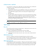
Configuring VRRP Overview Typically, you can configure a default gateway for every host on a LAN. All packets destined for other networks are sent through the default gateway. As shown in Figure 1, when the default gateway fails, no hosts can communicate with external networks. Figure 1 LAN networking Using a default gateway facilitates your configuration but requires high availability. Using more egress gateways improves link availability but introduces the problem of routing among the egresses.
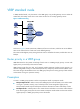
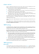
VRRP standard mode In VRRP standard mode, only the master in the VRRP group can provide gateway service. When the master fails, the backup routers elect a new master to take over for nonstop gateway service. Figure 2 VRRP networking As shown in Figure 2, Router A, Router B, and Router C form a virtual router, which has its own IP address. Hosts on the subnet use the virtual router as the default gateway.
Authentication method To avoid attacks from unauthorized users, VRRP member routers add authentication keys in VRRP packets to authenticate one another. VRRP provides the following authentication methods: • Simple authentication The sender fills an authentication key into the VRRP packet, and the receiver compares the received authentication key with its local authentication key. If the two authentication keys match, the received VRRP packet is legitimate.
Master election Routers in a VRRP group determine their roles by priority. When a router joins a VRRP group, it has a backup role. The router role changes according to the following situations: • If the backup does not receive any VRRP advertisement when the timer (3 × advertisement interval + Skew_Time) expires, it becomes the master. • If the backup receives a VRRP advertisement with a greater or the same priority within the timer (3 × advertisement interval + Skew_Time), it remains a backup.
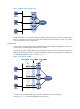
Figure 3 VRRP in master/backup mode Assume that Router A is acting as the master to forward packets to external networks, and Router B and Router C are backups in listening state. When Router A fails, Router B and Router C elect a new master to forward packets for hosts on the subnet. Load sharing A router can join multiple VRRP groups and has different priorities in different VRRP groups, and it can act as the master in one VRRP group and a backup in another.
• VRRP group 1—Router A is the master. Router B and Router C are the backups. • VRRP group 2—Router B is the master. Router A and Router C are the backups. • VRRP group 3—Router C is the master. Router A and Router B are the backups. To implement load sharing among Router A, Router B, and Router C, hosts on the subnet must be configured with the virtual IP addresses of VRRP group 1, 2, and 3 as default gateways, respectively.
Figure 5 Virtual MAC address assignment Network Router A Master Router B Backup Virtual IP: 10.1.1.1/24 Virtual MAC: 000f-e2ff-0011 Virtual MAC: 000f-e2ff-0012 Allocate Virtual MAC 000f-e2ff-0012 to Router B Gateway IP: 10.1.1.1/24 Gateway IP: 10.1.1.1/24 Host A 2. Host B When an ARP request arrives, the master (Router A) selects a virtual MAC address based on the load balancing algorithm to answer the ARP request.
Figure 7 Sending packets to different routers for forwarding Virtual forwarder Virtual forwarder creation Virtual MAC addresses enable traffic distribution across routers in a VRRP group. To enable routers in the VRRP group to forward packets, VFs must be created on them. Each VF is associated with a virtual MAC address in the VRRP group and forwards packets that are sent to this virtual MAC address. VFs are created on routers in a VRRP group, as follows: 1.
• On a router that does not own the VF, if the weight of the VF is higher than or equal to the lower limit of failure, the priority of the VF is calculated as weight/(number of local AVFs +1). • If the weight of the VF is lower than the lower limit of failure, the priority of the VF is 0. VF backup The VFs corresponding to a virtual MAC address on different routers in the VRRP group back up one another.
• Redirect timer—Before this timer expires, the master still uses the virtual MAC address corresponding to the failed AVF to respond to ARP/ND requests from hosts, and the VF owner can share traffic load if the VF owner resumes normal operation within this time. When this timer expires, the master stops using the virtual MAC address corresponding to the failed AVF to respond to ARP/ND requests from hosts.
Specifying an IPv4 VRRP operating mode A VRRP group can operate in either of the following modes: • Standard mode—Only the master can forward packets. • Load balancing mode—All members that have an AVF can forward packets. After an IPv4 VRRP operating mode is configured on a router, all IPv4 VRRP groups on the router operate in the specified operating mode. To specify an IPv4 VRRP operating mode: Step Enter system view. 1.
• In load balancing mode, the virtual IP address of a VRRP group can be any unassigned IP address of the subnet where the VRRP group resides, rather than the IP address of any interface in the VRRP group. No IP address owner can exist in a VRRP group.
Step Command Remarks 2. Enter interface view. interface interface-type interface-number N/A 3. Configure the priority of the router in the VRRP group. vrrp vrid virtual-router-id priority priority-value The default setting is 100. 4. Enable the preemptive mode for the router in a VRRP group and configure the preemption delay time.
Step Command Configure the interval at which the master in an IPv4 VRRP group sends VRRP advertisements. 4. Remarks The default setting is 100 centiseconds. vrrp vrid virtual-router-id timer advertise adver-interval To maintain system stability, HP recommends that you set the VRRP advertisement interval to be greater than 100 centiseconds. 5. Specify the source interface for receiving and sending VRRP packets.
Step 3. Configure the VFs in a VRRP group to monitor a track entry and configure the reduced weight. Command Remarks vrrp vrid virtual-router-id weight track track-entry-number [ reduced weight-reduced ] By default, no track entry is specified. Enabling SNMP notifications for VRRP Perform this task to enable VRRP to report important events through notifications to the SNMP module. The SNMP module determines how to output the notifications according to the configured output rules.
Task Command Clear statistics for IPv4 VRRP groups. reset vrrp statistics [ interface interface-type interface-number [ vrid virtual-router-id ] ] Configuring IPv6 VRRP This section describes how to configure IPv6 VRRP. IPv6 VRRP configuration task list Tasks at a glance Remarks (Required.) Specifying an IPv6 VRRP operating mode N/A (Required.) Creating a VRRP group and assigning a virtual IPv6 address N/A (Optional.
Creating a VRRP group and assigning a virtual IPv6 address A VRRP group can work correctly after you create it and assign at least one virtual IPv6 address for it. You can configure multiple virtual IPv6 addresses for the VRRP group on an interface that connects to multiple subnets for router backup.
Configuring the router priority, preemptive mode, and tracking function Configuration guidelines • The running priority of an IP address owner is always 255, and you do not need to configure it. An IP address owner always operates in preemptive mode. • If you associate a track entry with a VRRP group on an IP address owner, the association does not take effect until the router becomes a non-IP address owner.
Configuration procedure To configure VF tracking: Step Command Remarks 1. Enter system view. system-view N/A 2. Enter interface view. interface interface-type interface-number N/A 3. Configure the VFs in a VRRP group to monitor a track entry and configure the reduced weight. vrrp ipv6 vrid virtual-router-id weight track track-entry-number [ reduced weight-reduced ] By default, no track entry is specified.
Disabling an IPv6 VRRP group You can temporarily disable an IPv6 VRRP group. After being disabled, the VRRP group stays in initialized state, and its configurations remain unchanged. You can change the configuration of a VRRP group when it is disabled. Your changes take effect when you enable the VRRP group again. To disable an IPv6 VRRP group: Step Command Remarks 1. Enter system view. system-view N/A 2. Enter interface view. interface interface-type interface-number N/A 3.
Figure 9 Network diagram Configuration procedure 1. Configure Router A: # Specify an IP address for Router A. system-view [RouterA] interface ethernet 1/1 [RouterA-Ethernet1/1] ip address 10.1.1.1 255.255.255.0 # Create VRRP group 1 on Ethernet 1/1 and set its virtual IP address to 10.1.1.111. [RouterA-Ethernet1/1] vrrp vrid 1 virtual-ip 10.1.1.111 # Assign Router A a higher priority than Router B in VRRP group 1, so Router A can become the master.
Running Mode : Standard Total number of virtual routers : 1 Interface Ethernet1/1 VRID : 1 Adver Timer : 100 Admin Status : Up State : Master Config Pri : 110 Running Pri : 110 Preempt Mode : Yes Delay Time : 5 Auth Type : None Virtual IP : 10.1.1.111 Virtual MAC : 0000-5e00-0101 Master IP : 10.1.1.1 # Display detailed information about VRRP group 1 on Router B.
[RouterA-Ethernet1/1] display vrrp verbose IPv4 Virtual Router Information: Running Mode : Standard Total number of virtual routers : 1 Interface Ethernet1/1 VRID : 1 Adver Timer : 100 Admin Status : Up State : Master Config Pri : 110 Running Pri : 110 Preempt Mode : Yes Delay Time : 5 Auth Type : None Virtual IP : 10.1.1.111 Virtual MAC : 0000-5e00-0101 Master IP : 10.1.1.
[RouterA] interface ethernet 1/1 [RouterA-Ethernet1/1] ip address 10.1.1.1 255.255.255.0 # Create VRRP group 1 and set its virtual IP address to 10.1.1.111. [RouterA-Ethernet1/1] vrrp vrid 1 virtual-ip 10.1.1.111 # Assign Router A a higher priority than Router B in VRRP group 1, so Router A can become the master in the group. [RouterA-Ethernet1/1] vrrp vrid 1 priority 110 # Create VRRP group 2, and set its virtual IP address to 10.1.1.112. [RouterA-Ethernet1/1] vrrp vrid 2 virtual-ip 10.1.1.112 2.
# Display detailed information about the VRRP groups on Router B. [RouterB-Ethernet1/1] display vrrp verbose IPv4 Virtual Router Information: Running Mode : Standard Total number of virtual routers : 2 Interface Ethernet1/1 VRID : 1 Adver Timer : 100 Admin Status : Up State : Backup Config Pri : 100 Running Pri : 100 Preempt Mode : Yes Delay Time : 0 Become Master : 185ms left Auth Type : None Virtual IP : 10.1.1.111 Master IP : 10.1.1.
Figure 11 Network diagram Configuration procedure 1. Configure Router A: # Configure VRRP to operate in load balancing mode. system-view [RouterA] vrrp mode load-balance # Create VRRP group 1, and set its virtual IP address to 10.1.1.1. [RouterA] interface ethernet 1/1 [RouterA-Ethernet1/1] ip address 10.1.1.2 24 [RouterA-Ethernet1/1] vrrp vrid 1 virtual-ip 10.1.1.1 # Assign Router A the highest priority in VRRP group 1, so Router A can become the master.
# Configure VRRP to operate in load balancing mode. system-view [RouterB] vrrp mode load-balance # Create VRRP group 1, and set its virtual IP address to 10.1.1.1. [RouterB] interface ethernet 1/1 [RouterB-Ethernet1/1] ip address 10.1.1.3 24 [RouterB-Ethernet1/1] vrrp vrid 1 virtual-ip 10.1.1.1 # Assign Router B a higher priority than Router C in VRRP group 1, so Router B can become the master when Router A fails.
VRID : 1 Adver Timer : 100 Admin Status : Up State : Master Config Pri : 120 Running Pri : 120 Preempt Mode : Yes Delay Time : 5 Auth Type : None Virtual IP : 10.1.1.1 Member IP List : 10.1.1.2 (Local, Master) 10.1.1.3 (Backup) 10.1.1.
Forwarder Information: 3 Forwarders 1 Active Config Weight : 255 Running Weight : 255 Forwarder 01 State : Listening Virtual MAC : 000f-e2ff-0011 (Learnt) Owner ID : 0000-5e01-1101 Priority : 127 Active : 10.1.1.2 Forwarder 02 State : Active Virtual MAC : 000f-e2ff-0012 (Owner) Owner ID : 0000-5e01-1103 Priority : 255 Active : local Forwarder 03 State : Listening Virtual MAC : 000f-e2ff-0013 (Learnt) Owner ID : 0000-5e01-1105 Priority : 127 Active : 10.1.1.
Forwarder 02 State : Listening Virtual MAC : 000f-e2ff-0012 (Learnt) Owner ID : 0000-5e01-1103 Priority : 127 Active : 10.1.1.3 Forwarder 03 State : Active Virtual MAC : 000f-e2ff-0013 (Owner) Owner ID : 0000-5e01-1105 Priority : 255 Active : local Forwarder Weight Track Information: Track Object : 1 State : Positive Weight Reduced : 250 The output shows that Router A is the master in VRRP group 1, and each of the three routers has one AVF and two LVFs.
State : Initialize Virtual MAC : 000f-e2ff-0013 (Learnt) Owner ID : 0000-5e01-1105 Priority : 0 Active : 10.1.1.4 Forwarder Weight Track Information: Track Object : 1 State : Negative Weight Reduced : 250 # Display detailed information about VRRP group 1 on Router C.
forward traffic. The VF for MAC address 000f-e2ff-0011 on Router C becomes the AVF to forward traffic. # When the timeout timer (about 1800 seconds) expires, display detailed information about VRRP group 1 on Router C.
Virtual IP : 10.1.1.1 Member IP List : 10.1.1.3 (Local, Master) 10.1.1.4 (Backup) Forwarder Information: 2 Forwarders 1 Active Config Weight : 255 Running Weight : 255 Forwarder 02 State : Active Virtual MAC : 000f-e2ff-0012 (Owner) Owner ID : 0000-5e01-1103 Priority : 255 Active : local Forwarder 03 State : Listening Virtual MAC : 000f-e2ff-0013 (Learnt) Owner ID : 0000-5e01-1105 Priority : 127 Active : 10.1.1.
Figure 12 Network diagram Configuration procedure 1. Configure Router A: # Specify an IPv6 address for Router A. system-view [RouterA] interface ethernet 1/1 [RouterA-Ethernet1/1] ipv6 address fe80::1 link-local [RouterA-Ethernet1/1] ipv6 address 1::1 64 # Create VRRP group 1, and set its virtual IPv6 addresses to FE80::10 and 1::10.
[RouterB-Ethernet1/1] undo ipv6 nd ra halt 3. Verify the configuration: # Ping Host B from Host A. (Details not shown.) # Display detailed information about VRRP group 1 on Router A.
Auth Type : None Virtual IP : FE80::10 Virtual MAC : 0000-5e00-0201 Master IP : FE80::2 1::10 The output shows that when Router A fails, Router B takes over to forward packets from Host A to Host B. # Recover the link between Host A and Router A, and display detailed information about VRRP group 1 on Router A.
Figure 13 Network diagram Configuration procedure 1. Configure Router A: # Specify an IPv6 address for Router A. system-view [RouterA] interface ethernet 1/1 [RouterA-Ethernet1/1] ipv6 address fe80::1 link-local [RouterA-Ethernet1/1] ipv6 address 1::1 64 # Create VRRP group 1, and set its virtual IPv6 addresses to FE80::10 to 1::10.
# Assign Router B a higher priority than Router A in VRRP group 2, so Router B can become the master in the group. [RouterB-Ethernet1/1] vrrp ipv6 vrid 2 priority 110 3. Verify the configuration: # Display detailed information about the VRRP groups on Router A.
Admin Status : Up State : Master Config Pri : 110 Running Pri : 110 Preempt Mode : Yes Delay Time : 0 Auth Type : None Virtual IP : FE80::20 1::20 Virtual MAC : 0000-5e00-0202 Master IP : FE80::2 The output shows that Router A is operating as the master in VRRP group 1 to forward Internet traffic for hosts that use the default gateway 1::10/64. Router B is operating as the master in VRRP group 2 to forward Internet traffic for hosts that use the default gateway 1::20/64.
Configuration procedure 1. Configure Router A: # Configure VRRP to operate in load balancing mode. system-view [RouterA] vrrp ipv6 mode load-balance # Create VRRP group 1, and set its virtual IPv6 addresses to FE80::10 and 1::10.
[RouterB-Ethernet1/1] quit # Create track entry 1 to monitor the upstream link status of Ethernet 1/2. When the upstream link fails, the track entry transits to Negative. [RouterB] track 1 interface ethernet 1/2 # Configure the VFs in VRRP group 1 to monitor track entry 1, and decrease their weights by 250 when the track entry transits to Negative. [RouterB] interface ethernet 1/1 [RouterB-Ethernet1/1] vrrp ipv6 vrid 1 weight track 1 reduced 250 3.
Member IP List : FE80::1 (Local, Master) FE80::2 (Backup) FE80::3 (Backup) Forwarder Information: 3 Forwarders 1 Active Config Weight : 255 Running Weight : 255 Forwarder 01 State : Active Virtual MAC : 000f-e2ff-4011 (Owner) Owner ID : 0000-5e01-1101 Priority : 255 Active : local Forwarder 02 State : Listening Virtual MAC : 000f-e2ff-4012 (Learnt) Owner ID : 0000-5e01-1103 Priority : 127 Active : FE80::2 Forwarder 03 State : Listening Virtual MAC : 000f-e2ff-4013 (Learnt) Owner ID
Virtual MAC : 000f-e2ff-4011 (Learnt) Owner ID : 0000-5e01-1101 Priority : 127 Active : FE80::1 Forwarder 02 State : Active Virtual MAC : 000f-e2ff-4012 (Owner) Owner ID : 0000-5e01-1103 Priority : 255 Active : local Forwarder 03 State : Listening Virtual MAC : 000f-e2ff-4013 (Learnt) Owner ID : 0000-5e01-1105 Priority : 127 Active : FE80::3 Forwarder Weight Track Information: Track Object : 1 State : Positive Weight Reduced : 250 # Display detailed information about VRRP gro
Priority : 127 Active : FE80::2 Forwarder 03 State : Active Virtual MAC : 000f-e2ff-4013 (Owner) Owner ID : 0000-5e01-1105 Priority : 255 Active : local Forwarder Weight Track Information: Track Object : 1 State : Positive Weight Reduced : 250 The output shows that Router A is the master in VRRP group 1, and each of the three routers has one AVF and two LVFs. # Disconnect the link of Ethernet 1/2 on Router A, and display detailed information about VRRP group 1 on Router A.
Priority : 0 Active : FE80::3 Forwarder Weight Track Information: Track Object : 1 State : Negative Weight Reduced : 250 # Display detailed information about VRRP group 1 on Router C.
# When the timeout timer (about 1800 seconds) expires, display detailed information about VRRP group 1 on Router C.
Virtual IP : FE80::10 1::10 Member IP List : FE80::2 (Local, Master) FE80::3 (Backup) Forwarder Information: 2 Forwarders 1 Active Config Weight : 255 Running Weight : 255 Forwarder 02 State : Active Virtual MAC : 000f-e2ff-4012 (Owner) Owner ID : 0000-5e01-1103 Priority : 255 Active : local Forwarder 03 State : Listening Virtual MAC : 000f-e2ff-4013 (Learnt) Owner ID : 0000-5e01-1105 Priority : 127 Active : FE80::3 Forwarder Weight Track Information: Track Object : 1 State : Posit
Multiple masters appear in a VRRP group Symptom Multiple masters appear in a VRRP group. Analysis It is normal for a VRRP group to have multiple masters for a short time, and this situation requires no manual intervention. If multiple masters coexist for a longer period, it might be because the masters cannot receive advertisements from each other, or because the received advertisements are illegitimate.
Configuring BFD Introduction to BFD Bidirectional forwarding detection (BFD) provides a general-purpose, standard, medium- and protocol-independent fast failure detection mechanism. It can detect and monitor the connectivity of links in IP to detect communication failures quickly so that measures can be taken to ensure service continuity and enhance network availability.
Echo packet mode The local end of the link sends echo packets to establish BFD sessions and monitor link status. The peer end does not establish BFD sessions and only forwards the packets back to the originating end. In echo packet mode, BFD supports only single-hop detection and the BFD session is independent of the operating mode. Control packet mode Both ends of the link exchange BFD control packets to monitor link status.
Protocols and standards • RFC 5880, Bidirectional Forwarding Detection (BFD) • RFC 5881, Bidirectional Forwarding Detection (BFD) for IPv4 and IPv6 (Single Hop) • RFC 5882, Generic Application of Bidirectional Forwarding Detection (BFD) • RFC 5883, Bidirectional Forwarding Detection (BFD) for Multihop Paths • RFC 5884, Bidirectional Forwarding Detection (BFD) for MPLS Label Switched Paths (LSPs) • RFC 5885, Bidirectional Forwarding Detection (BFD) for the Pseudowire Virtual Circuit Connectivity V
Configuring control packet mode To configure control packet mode for single-hop detection: Step Command Remarks 1. Enter system view. system-view N/A 2. Specify the mode for establishing a BFD session. bfd session init-mode { active | passive } By default, active is specified. 3. Enter interface view. interface interface-type interface-number N/A 4. Configure the authentication mode for single-hop control packets.
Step Command Remarks 5. Configure the multi-hop detection time multiplier. bfd multi-hop detect-multiplier value The default setting is 5. 6. Configure the minimum interval for receiving multi-hop BFD control packets. bfd multi-hop min-receive-interval value The default setting is 1000 milliseconds. 7. Configure the minimum interval for transmitting multi-hop BFD control packets. bfd multi-hop min-transmit-interval value The default setting is 1000 milliseconds.
Configuring Track Overview The Track module works between application modules and detection modules, as shown in Figure 15. It shields the differences between various detection modules from application modules. Collaboration is enabled after you associate the Track module with a detection module and an application module. The detection module probes specific objects such as interface status, link status, network reachability, and network performance, and informs the Track module of detection results.
• BFD. • Interface management. Collaboration between the Track module and an application module The following application modules can be associated with the Track module: • VRRP. • Static routing. • Policy-based routing. When you configure a track entry for an application module, you can set a notification delay to avoid immediate notification of status changes, which can cause communication failure. This issue occurs when route convergence is slower than the link state change notification.
Tasks at a glance Remarks (Required.) Associating the Track module with an application module: • Associating Track with VRRP • Associating Track with static routing • Associating Track with PBR Use one of the methods. Associating the Track module with a detection module Associating Track with NQA NQA supports multiple test types to analyze network performance, services, and service quality.
• If the BFD detects that the link fails, it informs the track entry of the link failure. The Track module sets the track entry to Negative state. • If the BFD detects that the link is operating correctly, the Track module sets the track entry to Positive state. Configuration prerequisites Before you associate Track with BFD, configure the source IP address of BFD echo packets. For more information, see "Configuring BFD." Configuration procedure To associate Track with BFD: Step 1. Enter system view.
Step Command Remarks • Create a track entry, associate it with 2. Associating Track with interface management.
Monitor the AVF status from the LVF, which refers to the VF in listening state. When the AVF fails, the LVF that is operating in switchover mode becomes the new AVF to ensure continuous forwarding. • Follow these guidelines when you associate Track with VRRP: • VRRP tracking is not valid on an IP address owner. An IP address owner refers to a router when the IP address of the virtual router is the IP address of an interface on the router in the VRRP group.
To prevent this problem, configure another route to back up the static route. When the static route is reachable, packets are forwarded through the static route. When the static route is unreachable, packets are forwarded through the backup route, avoiding network breaks and enhancing network reliability. To check the accessibility of a static route in real time, establish an association between Track and the static route.
Associating Track with PBR PBR is a routing mechanism based on user-defined policies. Different from the traditional destination-based routing mechanism, PBR allows you to use a policy (based on such criteria as the source address and packet length) to route packets. You can specify the VPN instance, packet priority, outgoing interface, next hop, default outgoing interface, default next hop, and other parameters to guide the forwarding of packets that match specific ACLs or have specific lengths.
Step Command Remarks • Define a packet length match criterion: if-match packet-length min-len max-len 3. Define a match criterion. • Define an ACL match criterion: if-match acl { acl-number | name acl-name } By default, no packets are filtered. • Set the outgoing interface, and associate it with a track entry: apply output-interface { interface-type interface-number [ track track-entry-number ] }&<1-n> • Set the next hop, and associate it with a 4. Associate Track with PBR.
Step Command Remarks • Set the outgoing interface, and associate it with a track entry: apply output-interface { interface-type interface-number [ track track-entry-number ] }&<1-n> • Set the next hop, and associate it with a 4. Associate Track with IPv6 PBR. track entry: apply next-hop [ vpn-instance vpn-instance-name | inbound-vpn ] { ipv6-address [ direct ] [ track track-entry-number ] }&<1-n> • Set the default outgoing interface, and Use at least one of the commands.
Figure 16 Network diagram Configuration procedure 1. Configure the IP address of each interface as shown in Figure 16. (Details not shown.) 2. Configure an NQA test group on Router A: # Create an NQA test group with the administrator name admin and the operation tag test. system-view [RouterA] nqa entry admin test # Configure the test type as ICMP echo test. [RouterA-nqa-admin-test] type icmp-echo # Configure the destination address as 10.1.2.2.
[RouterA-Ethernet1/1] vrrp vrid 1 authentication-mode simple plain hello # Configure the master to send VRRP packets at an interval of 500 centiseconds. [RouterA-Ethernet1/1] vrrp vrid 1 timer advertise 500 # Configure Router A to operate in preemptive mode, and set the preemption delay to 5 seconds. [RouterA-Ethernet1/1] vrrp vrid 1 preempt-mode delay 5 # Configure to monitor track entry 1 and specify the priority decrement to 30. [RouterA-Ethernet1/1] vrrp vrid 1 track 1 reduced 30 5.
Config Pri : 100 Running Pri : 100 Preempt Mode : Yes Delay Time : 5 Become Master : 2200ms left Auth Type : Simple Key : ****** Virtual IP : 10.1.1.10 Master IP : 10.1.1.1 The output shows that in VRRP group 1, Router A is the master and Router B is a backup. Packets from Host A to Host B are forwarded through Router A. When a fault is on the link between Router A and Router C, you can still successfully ping Host B on Host A.
Configuring BFD for a VRRP backup to monitor the master Network requirements As shown in Figure 17, Router A and Router B belong to VRRP group 1, whose virtual IP address is 192.168.0.10. The default gateway of the hosts in the LAN is 192.168.0.10. When Router A works correctly, the hosts in the LAN access the external network through Router A. When Router A fails, the hosts in the LAN access the external network through Router B.
# Configure the source address of BFD echo packets as 10.10.10.10. system-view [RouterB] bfd echo-source-ip 10.10.10.10 3. Create a track entry to be associated with the BFD session on Router B: # Create track entry 1 to be associated with the BFD session to check whether Router A is reachable. [RouterB] track 1 bfd echo interface ethernet 1/1 remote ip 192.168.0.101 local ip 192.168.0.102 4. Configure VRRP on Router B: # Create VRRP group 1, and configure the virtual IP address 192.168.0.
# Display information about track entry 1 on Router B. display track 1 Track ID: 1 State: Positive Duration: 0 days 0 hours 0 minutes 32 seconds Notification delay: Positive 0, Negative 0 (in seconds) Tracked object: BFD session mode: Echo Outgoing Interface: Ethernet1/1 VPN instance name: Remote IP: 192.168.0.101 Local IP: 192.168.0.102 The output shows that when the status of the track entry becomes Positive, Router A is the master, and Router B the backup.
Configuring BFD for the VRRP master to monitor the uplink Network requirements As shown in Figure 18, Router A and Router B belong to VRRP group 1, whose virtual IP address is 192.168.0.10. The default gateway of the hosts in the LAN is 192.168.0.10. When Router A works correctly, hosts in the LAN access the external network through Router A.
the status of track entry 1. When the status of the track entry becomes Negative, the priority of Router A decreases by 20. [RouterA] interface ethernet 1/2 [RouterA-Ethernet1/2] vrrp vrid 1 virtual-ip 192.168.0.10 [RouterA-Ethernet1/2] vrrp vrid 1 priority 110 [RouterA-Ethernet1/2] vrrp vrid 1 track 1 reduced 20 [RouterA-Ethernet1/2] return 4. Configure VRRP on Router B: # Create VRRP group 1, and configure the virtual IP address of the group as 192.168.0.10.
Total number of virtual routers : 1 Interface Ethernet1/2 VRID : 1 Adver Timer : 100 Admin Status : Up State : Backup Config Pri : 100 Running Pri : 100 Preempt Mode : Yes Delay Time : 0 Become Master : 2200ms left Auth Type : None Virtual IP : 192.168.0.10 Master IP : 192.168.0.101 The output shows that when the status of track entry 1 becomes Positive, Router A is the master and Router B the backup.
Admin Status : Up State : Master Config Pri : 100 Running Pri : 100 Preempt Mode : Yes Delay Time : 0 Auth Type : None Virtual IP : 192.168.0.10 Virtual MAC : 0000-5e00-0101 Master IP : 192.168.0.102 The output shows that when Router A detects that the uplink fails through BFD, it decreases its priority by 20 to make sure that Router B can preempt as the master.
Figure 19 Network diagram Configuration procedure 1. Configure the IP address of each interface as shown in Figure 19. (Details not shown.) 2. Configure Router A: # Configure a static route to 30.1.1.0/24, with the address of the next hop as 10.1.1.2 and the default priority 60. This static route is associated with track entry 1. system-view [RouterA] ip route-static 30.1.1.0 24 10.1.1.2 track 1 # Configure a static route to 30.1.1.0/24, with the address of the next hop as 10.3.1.
[RouterA] nqa schedule admin test start-time now lifetime forever # Configure track entry 1, and associate it with reaction entry 1 of the NQA test group (with the administrator admin, and the operation tag test). [RouterA] track 1 nqa entry admin test reaction 1 3. Configure Router B: # Configure a static route to 30.1.1.0/24, with the address of the next hop as 10.2.1.4. system-view [RouterB] ip route-static 30.1.1.0 24 10.2.1.4 # Configure a static route to 20.1.1.
[RouterD] track 1 nqa entry admin test reaction 1 Verifying the configuration # Display information about the track entry on Router A. [RouterA] display track all Track ID: 1 State: Positive Duration: 0 days 0 hours 0 minutes 32 seconds Notification delay: Positive 0, Negative 0 (in seconds) Tracked object: NQA entry: admin test Reaction: 1 # Display the routing table of Router A. [RouterA] display ip routing-table Routing Tables: Public Destinations : 10 Destination/Mask Proto 10.1.1.0/24 10.1.1.
Destinations : 10 Destination/Mask Proto 10.1.1.0/24 10.1.1.1/32 Routes : 10 Pre Cost NextHop Interface Direct 0 0 10.1.1.1 Eth1/1 Direct 0 0 127.0.0.1 InLoop0 10.2.1.0/24 Static 60 0 10.1.1.2 Eth1/1 10.3.1.0/24 Direct 0 0 10.3.1.1 Eth1/2 10.3.1.1/32 Direct 0 0 127.0.0.1 InLoop0 20.1.1.0/24 Direct 0 0 20.1.1.1 Eth1/3 20.1.1.1/32 Direct 0 0 127.0.0.1 InLoop0 30.1.1.0/24 Static 80 0 10.3.1.3 Eth1/2 127.0.0.0/8 Direct 0 0 127.0.0.1 InLoop0 127.0.0.
Static routing-Track-BFD collaboration configuration example Network requirements As shown in Figure 20, Router A, Router B, and Router C are connected to two segments 20.1.1.0/24 and 30.1.1.0/24. Configure static routes on these routers so that the two segments can communicate with each other. Configure route backup to improve network reliability. Router A is the default gateway of the hosts in segment 20.1.1.0/24. Two static routes to 30.1.1.
[RouterA] ip route-static 30.1.1.0 24 10.3.1.3 preference 80 # Configure the source address of BFD echo packets as 10.10.10.10. [RouterA] bfd echo-source-ip 10.10.10.10 # Configure track entry 1, and associate it with the BFD session. Check whether Router A can be interoperated with the next hop of static route, which is Router B. [RouterA] track 1 bfd echo interface ethernet 1/1 remote ip 10.2.1.2 local ip 10.2.1.1 3. Configure Router B: # Configure a static route to 20.1.1.
10.2.1.0/24 Direct 0 0 10.2.1.1 Eth1/1 10.2.1.1/32 Direct 0 0 127.0.0.1 InLoop0 10.3.1.0/24 Direct 0 0 10.3.1.1 Eth1/2 10.3.1.1/32 Direct 0 0 127.0.0.1 InLoop0 20.1.1.0/24 Direct 0 0 20.1.1.1 Eth1/3 20.1.1.1/32 Direct 0 0 127.0.0.1 InLoop0 30.1.1.0/24 Static 60 0 10.2.1.2 Eth1/1 127.0.0.0/8 Direct 0 0 127.0.0.1 InLoop0 127.0.0.1/32 Direct 0 0 127.0.0.1 InLoop0 The output shows the BFD detection result: the next hop 10.2.1.
# When the master route fails, the hosts in 20.1.1.0/24 can still communicate with the hosts in 30.1.1.0/24. [RouterA] ping -a 20.1.1.1 30.1.1.1 Ping 30.1.1.1: 56 data bytes, press escape sequence to break Reply from 30.1.1.1: bytes=56 Sequence=1 ttl=254 time=2 ms Reply from 30.1.1.1: bytes=56 Sequence=2 ttl=254 time=1 ms Reply from 30.1.1.1: bytes=56 Sequence=3 ttl=254 time=1 ms Reply from 30.1.1.1: bytes=56 Sequence=4 ttl=254 time=2 ms Reply from 30.1.1.
Figure 21 Network diagram Configuration procedure 1. Configure the IP address of each interface as shown in Figure 21. (Details not shown.) 2. Configure a track entry on Router A: # Configure track entry 1, and associate it with the link status of the uplink interface Ethernet 1/2. [RouterA] track 1 interface ethernet 1/2 3. Configure VRRP on Router A: # Create VRRP group 1, and configure the virtual IP address 10.1.1.10 for the group.
Config Pri : 110 Running Pri : 110 Preempt Mode : Yes Delay Time : 0 Auth Type : None Virtual IP : 10.1.1.10 Virtual MAC : 0000-5e00-0101 Master IP : 10.1.1.1 VRRP Track Information: Track Object : 1 State : Positive Pri Reduced : 30 # Display detailed information about VRRP group 1 on Router B.
# After shutting down the uplink interface on Router A, display detailed information about VRRP group 1 on Router B. [RouterB-Ethernet1/1] display vrrp verbose IPv4 Virtual Router Information: Running Mode : Standard Total number of virtual routers : 1 Interface Ethernet1/1 VRID : 1 Adver Timer : 100 Admin Status : Up State : Master Config Pri : 100 Running Pri : 100 Preempt Mode : Yes Delay Time : 0 Auth Type : None Virtual IP : 10.1.1.
Configuring process placement Overview Process placement enables placing processes to specific CPUs (also called "nodes") on the main processing units (MPUs) in your system for optimal distribution of CPU and memory resources. Process A process comprises a set of codes and provides specific functionality. For example, an AAA process provides AAA functions. Each process runs in a protected memory space to prevent problems with one process from impacting the entire system.
• The addition of a new node does not impact current active processes. A new active process selects one node with sufficient CPU and memory resources. (You can use the display cpu-usage and display memory commands to view CPU and memory usage information.) Optimizing process placement You can configure the following settings for a process placement policy to optimize process placement: • affinity location-set—Location affinity, the preference for the process to run on a specific node.
Tasks at a glance • (Optional.) Configuring a process affinity • (Optional.) Configuring a self affinity (Required.) Optimizing process placement Configuring process placement policy Configuring a location affinity Step Enter system view. 1. Command Remarks system-view N/A Use either command. • Enter default placement process view: 2. 3. placement program default Enter placement process view. • Enter placement process view: Set the location affinity.
Step Command Remarks 3. affinity location-type { current | paired | primary } { attract strength | repulse strength | default | none } By default, no location type affinity is set. Set the location type affinity. Configuring a process affinity Step 1. Enter system view. Command Remarks system-view N/A • Enter default placement process view: placement program default 2. Enter placement process view. • Enter placement process view: placement program { program-name [ instance instance-name ] 3.
Optimizing process placement Step Command 1. Enter system view. system-view 2. Optimize process placement. placement reoptimize Displaying process placement Execute display commands in any view. Task Command Display process placement policy information. display placement policy program { program-name | all | default } Display the location of a process. display placement program { program-name | all } Display the running processes on a specific location.
Support and other resources Contacting HP For worldwide technical support information, see the HP support website: http://www.hp.
Conventions This section describes the conventions used in this documentation set. Command conventions Convention Description Boldface Bold text represents commands and keywords that you enter literally as shown. Italic Italic text represents arguments that you replace with actual values. [] Square brackets enclose syntax choices (keywords or arguments) that are optional. { x | y | ... } Braces enclose a set of required syntax choices separated by vertical bars, from which you select one.
Network topology icons Represents a generic network device, such as a router, switch, or firewall. Represents a routing-capable device, such as a router or Layer 3 switch. Represents a generic switch, such as a Layer 2 or Layer 3 switch, or a router that supports Layer 2 forwarding and other Layer 2 features. Represents an access controller, a unified wired-WLAN module, or the switching engine on a unified wired-WLAN switch. Represents an access point.
Index ACDIOPRTV A IPv6 VRRP configuration examples,33 Associating the Track module with a detection module,56 O Associating the Track module with an application module,58 Overview,85 C Overview,1 Configuration restrictions and guidelines,86 P Configuring BFD basic functions,51 Process placement configuration task list,86 Optimizing process placement,89 Overview,54 Configuring IPv4 VRRP,10 Protocols and standards,10 Configuring IPv6 VRRP,16 R Configuring process placement policy,87 Contactin