
HP MSR2000/3000/4000 Router Series High Availability Configuration Guide

82
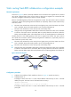
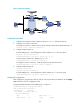
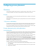
Figure 21 Network diagram
Configuration procedure
1. Configure the IP address of each interface as shown in Figure 21. (Details not shown.)
2. Configure a track entry on Router A:
# Configure track entry 1, and associate it with the link status of the uplink interface Ethernet 1/2.
[RouterA] track 1 interface ethernet 1/2
3. Configure VRRP on Router A:
# Create VRRP group 1, and configure the virtual IP address 10.1.1.10 for the group.
[RouterA] interface ethernet 1/1
[RouterA-Ethernet1/1] vrrp vrid 1 virtual-ip 10.1.1.10
# Set the priority of Router A in VRRP group 1 to 110.
[RouterA-Ethernet1/1] vrrp vrid 1 priority 110
# Configure to monitor track entry 1 and specify the priority decrement as 30.
[RouterA-Ethernet1/1] vrrp vrid 1 track 1 reduced 30
4. Configure VRRP on Router B:
<RouterB> system-view
[RouterB] interface ethernet 1/1
# Create VRRP group 1, and configure the virtual IP address 10.1.1.10 for the group.
[RouterB-Ethernet1/1] vrrp vrid 1 virtual-ip 10.1.1.10
Verifying the configuration
After configuration, ping Host B on Host A, and you can see that Host B is reachable. Use the display
vrrp command to view the configuration result.
# Display detailed information about VRRP group 1 on Router A.
[RouterA-Ethernet1/1] display vrrp verbose
IPv4 Virtual Router Information:
Running Mode : Standard
Total number of virtual routers : 1
Interface Ethernet1/1
VRID : 1 Adver Timer : 100
Admin Status : Up State : Master