
HP MSR2000/3000/4000 Router Series Interface Command Reference

47
Usage guidelines
A synchronous serial interface can operate as a DCE or DTE.
• As a DCE, the interface provides DCEclk clock to the DTE.
• As a DTE, the interface accepts the clock provided by the DCE. Because transmitting and receiving
clocks of synchronization devices are independent, the receiving clock of a DTE device can be
either the transmitting or receiving clock of the DCE device, so is the transmitting clock. Therefore,
five clock options are available for a DTE device.
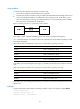
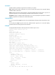
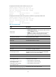
Figure 1 Selecting a clock for a synchronous serial interface
In the figure, "TxClk" represents transmitting clock, and "RxClk" represents receiving clock.
Table 8 de
scribes the four clock selection options for a synchronous serial interface operating as a DTE
and a DCE, respectively.
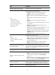
Table 8 Clock options available for a synchronous serial interface operating as a DTE
Clock selection o
p
tion Descri
p
tion
DTEclk1 TxClk = TxClk, RxClk = RxClk.
DTEclk2 TxClk = TxClk, RxClk = TxClk.
DTEclk3 TxClk = RxClk, RxClk = TxClk.
DTEclk4 TxClk = RxClk, RxClk = RxClk.
DTEclk5 TxClk = Local, RxClk = Local.
In the table, the clock preceding the equal sign (=) is the DTE clock and the one that follows is the DCE
clock.
Table 9 Clock options available for a synchronous serial interface operating as a DCE
Clock selection o
p
tion Descri
p
tion
DCEclk1 TxClk = Local, RxClk = Local.
DCEclk2 TxClk = Local, RxClk = Line.
DCEclk3 TxClk = Line, RxClk = Line.
In the table, the clock preceding the equal sign (=) is the DCE clock and the one that follows is the clock
signal source.
Examples
# Set the synchronous serial interface operating as a DTE to use the clock selection option dteclk2.
<Sysname> system-view
[Sysname] interface serial 2/0
[Sysname-Serial2/0] clock dteclk2