HP MSR2000/3000/4000 Router Series Interface Configuration Guide (V7) Part number: 5998-3987 Software version: CMW710-R0007P02 Document version: 6PW100-20130927
Legal and notice information © Copyright 2013 Hewlett-Packard Development Company, L.P. No part of this documentation may be reproduced or transmitted in any form or by any means without prior written consent of Hewlett-Packard Development Company, L.P. The information contained herein is subject to change without notice.
Contents Bulk configuring interfaces ···········································································································································ii Configuration guidelines ················································································································································· iii Configuration procedure ······································································································································
Displaying and maintaining CT1/PRI interfaces ································································································ 23 Configuring an E1-F interface ······································································································································· 23 Overview ································································································································································ 23 Configuration procedure
Failure to apply a command on one member interface does not affect the application of the command on the other member interfaces. If applying a command on one member interface fails, the system displays an error message and continues with the next member interface. Configuration guidelines When you bulk configure interfaces in interface range view, follow these restrictions and guidelines: • In interface range view, only the commands supported by the first interface are available.
Displaying and maintaining bulk interface configuration Execute the display command in any view. Task Command Display information about the specified interface range or all existing interface ranges.
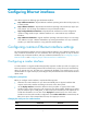
Configuring Ethernet interfaces Your device supports the following types of Ethernet interfaces: • Layer 2 Ethernet interfaces—Physical Ethernet interfaces operating at the data link layer (Layer 2) to switch packets. • Layer 3 Ethernet interfaces—Physical Ethernet interfaces operating at the network layer (Layer 3) to route packets. You can assign an IP address to a Layer 3 Ethernet interface.
Step Enter Ethernet interface view. 2. Command Remarks interface interface-type interface-number N/A By default, the copper combo port is active. Activate the copper combo port or fiber combo port. 3. combo enable { copper | fiber } When the loopback command is running on a combo interface, you cannot use the combo enable command on the combo interface.
Configuring the link mode of an Ethernet interface CAUTION: After you change the link mode of an Ethernet interface, all commands (except the shutdown command) on the Ethernet interface are restored to their defaults in the new link mode. Ethernet interfaces of the device can operate either as Layer 2 or Layer 3 Ethernet interfaces (you can set the link mode to bridge or route). To change the link mode of an Ethernet interface: Step Command Remarks 1. Enter system view. system-view N/A 2.
Performing an internal loopback test on an Ethernet interface If an Ethernet interface does not work correctly, you can perform an internal loopback test on it to test all on-chip functions related to the interface. An Ethernet interface in a loopback test does not forward data traffic. Configuration restrictions and guidelines • On an administratively shut down interface (displayed as in ADM or Administratively DOWN state), you cannot perform an internal loopback test.
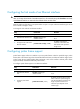
Setting the statistics polling interval Step Command Remarks 1. Enter system view. system-view N/A 2. Set the statistics polling interval. flow-interval interval By default, the interface statistics polling interval is 300 seconds. To display the interface statistics collected in the last polling interval, use the display interface command. To clear interface statistics, use the reset counters interface command.
Setting the MDIX mode of an Ethernet interface IMPORTANT: Fiber ports do not support the MDIX mode setting. A physical Ethernet interface comprises eight pins, each of which plays a dedicated role. For example, pins 1 and 2 transmit signals, and pins 3 and 6 receive signals. You can use both crossover and straight-through Ethernet cables to connect copper Ethernet interfaces.
Step Command Remarks 1. Enter system view. system-view N/A 2. Enter Ethernet interface or subinterface view. interface interface-type { interface-number | interface-number.subnumber } N/A 3. Set the MTU. mtu size The default setting is 1500 bytes. Configuring the MAC address of an Ethernet interface or subinterface In a network, when the Layer 3 Ethernet interfaces or subinterfaces of different devices have the same MAC address, the devices might fail to communicate correctly.
Task Command Display traffic rate statistics of interfaces in up state over the last sampling interval. display counters rate { inbound | outbound } interface [ interface-type [ interface-number | interface-number.subnumber ] ] Display the operational and status information of the specified interface or all interfaces. display interface [ interface-type [ interface-number | interface-number.subnumber ] ] Display summary information about the specified interface or all interfaces.
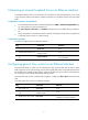
Configuring WAN interfaces This chapter describes how to configure interfaces for connecting to WAN networks, including ATM and ISDN. Available WAN interfaces include the asynchronous serial interface, synchronous serial interface, ATM interface, ISDN BRI interface, and CE1/PRI interface. For more information about ATM interfaces, see "Configuring ATM and DSL interfaces.
Step 2. Command Enter asynchronous serial interface view. Remarks interface async interface-number or N/A interface serial interface-number By default, the description of an asynchronous serial interface is interface name Interface, for example, Serial2/0 Interface. 3. (Optional.) Set the interface description. 4. Configure a synchronous or asynchronous serial interface to operate as an asynchronous serial interface. physical-mode async 5. Set the link layer protocol.
Step Command Remarks 1. Enter system view. system-view N/A 2. Enter synchronous serial interface view. interface serial interface-number N/A 3. Configure a synchronous or asynchronous serial interface to operate as a synchronous serial interface. physical-mode sync By default, a synchronous or asynchronous serial interface operates as a synchronous serial interface. 4. (Optional.) Set the interface description.
Step Command Remarks 19. (Optional.) Set the intended bandwidth for the synchronous serial interface. bandwidth bandwidth-value By default, the expected bandwidth (in kbps) is the interface baud rate divided by 1000. 20. (Optional.) Restore the default settings for the synchronous serial interface. default N/A 21. Bring up the synchronous serial interface. undo shutdown By default, a synchronous serial interface is up.
Configuration procedure The configuration of AM interface is similar to that of asynchronous interface and modem, except that an AM interface does not support the modem auto-answer and the baudrate commands. For more information about modem configuration, see Layer 2—WAN Configuration Guide. To set the baud rate for an AM interface, use the speed command in user line view. For more information, see Fundamentals Configuration Guide.
Displaying and maintaining AM interfaces Execute display commands in any view and reset commands in user view. Task Command display interface [ analogmodem ] [ brief [ down ] ] Display information about the specified AM interfaces. display interface [ analogmodem [ interface-number ] ] [ brief [ description ] ] reset counters interface [ analogmodem [ interface-number ] ] Clear statistics on a specified AM interface.
• Category-2 terminal equipment (TE2), or named non-ISDN standard terminal equipment, refers to the user equipment incompliant with the ISDN interface provisions. • Terminal adapter (TA) implements the adaptation function so that TE2 can access a standard ISDN interface. Reference points include: • R reference point between a non-ISDN equipment and TA. • S reference point between a user terminal and NT2. • T reference point between NT1 and NT2. • U reference point between NT1 and line terminal.
Step Command Remarks 6. Set the keepalive transmission interval. timer-hold seconds The default is 10 seconds. 7. Set the intended bandwidth for the BRI interface. bandwidth bandwidth-value By default, the expected bandwidth (in kbps) is the interface baud rate divided by 1000. 8. (Optional.) Restore the default settings for the BRI interface. default N/A 9. (Optional.) Bring up the BRI interface. undo shutdown By default, a BRI interface is up.
timeslot bundling. Its logical features are the same as those of a synchronous serial interface. It supports link layer protocols such as PPP, HDLC, FR, LAPB, and X.25, and network protocols such as IP. { When the interface is used as a PRI interface, timeslot 16 will be used as a D channel to transmit signaling. Therefore, rather than selecting among all the timeslots, you are only allowed to make a random B channel selection among the timeslot sets except timeslots 0 and 16.
Step Command Remarks By default, no channel set is created. 4. Bundle timeslots on the interface into a channel set. channel-set set-number timeslot-list list The timeslots on a CE1/PRI interface can be bundled into either channel sets or a PRI set, but not the both, at a time. 5. Set the framing format. frame-format { crc4 | no-crc4 } The default is no-CRC4. 6. (Optional.) Enable RAI detection on the interface. alarm detect rai By default, RAI detection is enabled on the interface. 7.
For the PRI set, the system automatically creates a serial interface numbered serial interface-numbe:15. This interface is logically equivalent to an ISDN PRI interface where you can make other configurations such as: • DCC • PPP and PPP authentication • IP addressing • Backup center settings if the interface is to be used as a primary or secondary interface for backup • Firewall Configuring other CE1/PRI interface parameters Step Command Remarks 1. Enter system view. system-view N/A 2.
Step Command Remarks 17. Set the CRC mode crc { 16 | 32 | none } By default, 16-bit CRC is adopted. Displaying and maintaining CE1/PRI interfaces Execute display commands in any view and reset commands in user view. Task Command Display the status of a CE1/PRI interface. display controller e1 [interface-number ] Display the status of a channel set or PRI set. display interface serial interface-number:set-number Clear the controller counter for a CE1/PRI interface.
For each channel set, the system automatically creates a serial interface numbered serial number:set-number. This interface is logically equivalent to a synchronous serial interface where you can make other configurations about: • Data link protocol such as PPP. • IP addressing. • Backup center settings if the interface is used as a primary or secondary interface for backup. • NAT and packet filtering if a firewall is to be set up.
Step Command Remarks 6. Set the clock mode. clock { master | slave } The default is slave, which is line clock. 7. Set the framing format. frame-format { sf | esf } The default is ESF. 8. Enable RAI detection on the interface. alarm detect rai Enable user data inversion. data-coding { normal | inverted } By default, user data inversion is disabled. 10. Set the line idle code type. idlecode { 7e | ff } The default is 0x7E. 11. Set the type of interframe filling tag.
Starting/terminating a BERT test on a CT1/PRI interface Bit error rate test (BERT) operates as follows: The local end sends out a pattern, which is to be looped over somewhere on the line and back to the local end. The local end then checks the received pattern for the bit error rate, and by so doing helps you determine whether the condition of the line is good.
When an E1-F interface is operating in unframed mode, it is a non-timeslot interface with 2048 kbps of data bandwidth. It is logically equivalent to a synchronous serial interface where you can configure PPP, HDLC, FR, LAPB or X.25 at the link layer and IP at the network layer. When an E1-F interface is operating in framed mode, it is physically divided into 32 timeslots numbered 0 through 31.
Configuring other E1-F interface parameters Step Command Remarks 1. Enter system view. system-view N/A 2. Enter E1-F interface view. interface serial serial-number N/A 3. Configure the interface description. description text By default, the description of an interface is interface-name Interface. 4. Set the line code format. fe1 code { ami | hdb3 } The default is HDB3. 5. Set the clock mode. fe1 clock { master | slave } The default is slave, which is line clock. 6.
Task Command Display the status of an E1-F interface. display interface serial interface-number Clear the controller counter of a E1-F interface. reset counters interface [ serial [ interface-number ] ] Configuring a T1-F interface Overview T1-F interfaces, fractional T1 interfaces, are simplified CT1/PRI interfaces. They are a cost-effective alternative to CT1/PRI interfaces where T1 access does not need multiple channel sets or ISDN PRI.
Step Command Remarks 6. Set the line code format. ft1 code { ami | b8zs } The default is B8ZS. 7. Set the clock mode. ft1 clock { master | slave } The default is slave, which is line clock. 8. Set the framing format. ft1 frame-format { esf | sf } The default is esf. 9. (Optional.) Enable RAI detection on the interface. ft1 alarm detect rai By default, RAI detection is enabled on the interface. This command is applicable when the framing format is ESF. 10. (Optional.
Step Command Remarks 22. (Optional.) Restore the default settings for the T1-F interface. default N/A 23. Bring up the T1-F interface. undo shutdown By default, a T1-F interface is up. Starting/terminating a BERT test on a T1-F interface BERT is operating as follows: The local end sends out a pattern, which is to be looped over somewhere on the line and back to the local end.
• A CE3 interface in E3 mode is an interface with 34.368 Mbps data bandwidth, on which, no timeslots are divided. The system automatically creates a serial interface numbered serial number/line-number/0:0 for it. This interface operates at 34.368 Mbps and is logically equivalent to a synchronous serial interface where you can make other configurations. • A CE3 interface in CE3 mode can demultiplex 16 channels of E1 signals in compliance with ITU-T G.751 and G.742.
Step Command Remarks By default, a CE3 interface is up. 11. (Optional.) Bring up the CE3 interface. undo shutdown Use this command with caution, because once an interface is shut down, it stops operating. 12. Return to system view. quit N/A • interface serial number/line-number:0 13. Enter synchronous serial interface view of an interface formed by a CE3 interfaces. • interface serial N/A 14. Set the CRC mode. crc { 16 | 32 | none } By default, 16-bit CRC is adopted.
Step 5. (Optional.) Configure the interface description. 6. (Optional.) Configure the CE3 interface to perform BERT test, and configure the CE3 interface to perform BERT test on an E1 channel created on the interface. Command Remarks description text By default, the description of an interface is interface-name Interface.
Task Command Display the configuration and state of a serial interface formed on a CE3 interface. display interface serial interface-number Clear the controller counter of a CE3 interface.
Configuring POS interfaces The following matrix shows the POS interface feature and router compatibility: Feature MSR2000 MSR3000 MSR4000 POS interface No Yes Yes Overview SONET Synchronous Optical Network (SONET) adopts optical transmission. It is a synchronous transmission system defined by the ANSI and is an international standard transmission protocol. SDH ITU-T Synchronous Digital Hierarchy (SDH) uses a SONET rate subset.
Configuring a POS interface Step Command Remarks 1. Enter system view. system-view N/A 2. Enter POS interface view. interface pos interface-number N/A 3. Set the interface description. description text By default, the description of a POS interface is interface name Interface, for example, Pos5/0 Interface. 4. Set the polling interval. timer-hold seconds The default setting is 10 seconds. 5. Set the clock mode. clock { master | slave } The default setting is slave. 6.
Displaying and maintaining POS interfaces Execute display commands in any view and reset commands in user view. Task Command Display information about one or all POS interfaces. display interface [ pos ] [ brief [ down ] ] Clear statistics of one or all POS interfaces.
[RouterB-Pos1/0] shutdown [RouterB-Pos1/0] undo shutdown Verifying the configuration Check the interface connectivity between the POS interfaces with the display interface pos command and test network connectivity with the ping command. Troubleshooting POS interfaces Symptom 1 The physical state of POS interface is down. Solution • Check that the transmitting and receiving fibers-optic are correctly connected to the POS interface.
37
Configuring loopback, null, and inloopback interfaces This chapter describes how to configure a loopback interface, a null interface, and an inloopback interface. Configuring a loopback interface A loopback interface is a virtual interface. The physical layer state of a loopback interface is always up unless the loopback interface is manually shut down.
Configuring a null interface A null interface is a virtual interface and is always up, but you can neither use it to forward data packets nor can you configure it with an IP address or link layer protocol. The null interface provides a simpler way to filter packets than ACL. You can filter undesired traffic by transmitting it to a null interface instead of applying an ACL.
Task Command Clear the statistics on the inloopback interface.
Support and other resources Contacting HP For worldwide technical support information, see the HP support website: http://www.hp.
Conventions This section describes the conventions used in this documentation set. Command conventions Convention Description Boldface Bold text represents commands and keywords that you enter literally as shown. Italic Italic text represents arguments that you replace with actual values. [] Square brackets enclose syntax choices (keywords or arguments) that are optional. { x | y | ... } Braces enclose a set of required syntax choices separated by vertical bars, from which you select one.
Network topology icons Represents a generic network device, such as a router, switch, or firewall. Represents a routing-capable device, such as a router or Layer 3 switch. Represents a generic switch, such as a Layer 2 or Layer 3 switch, or a router that supports Layer 2 forwarding and other Layer 2 features. Represents an access controller, a unified wired-WLAN module, or the switching engine on a unified wired-WLAN switch. Represents an access point.
Index CDORT C Configuring common Ethernet interface settings,1 Configuration example for directly connecting routers through POS interfaces,35 Conventions,42 Contacting HP,41 Configuration guidelines,iii D Configuration procedure,iii Displaying and maintaining an Ethernet interface or subinterface,7 Configuring a CE1/PRI interface,16 Displaying and maintaining bulk interface configuration,iv Configuring a CE3 interface,28 Configuring a CT1/PRI interface,20 Displaying and maintaining loopback, nu