
HP MSR2000/3000/4000 Router Series Interface Module Guide


95
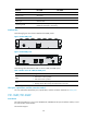
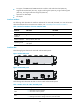
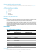
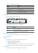
Figure 99 DFIC-24FSW panel
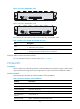
DFIC-24FSW-PoE panel is shown in the following figure:
Figure 100 DFIC-24FSW-PoE panel
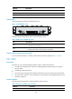
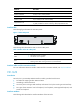
On the FIC-16FSW/FIC-16FSW-PoE/DFIC-24FSW/DFIC-24FSW-PoE panel, each port on the network
connector corresponds to one green LED. The following table describes the LEDs on the
FIC-16FSW/FIC-16FSW-PoE/DFIC-24FSW/DFIC-24FSW-PoE panel.
Table 136 LEDs on the FIC-16FSW/FIC-16FSW-PoE/DFIC-24FSW/DFIC-24FSW-PoE FE interface
LED Descri
p
tion
Steady green A link is present, but no data is being transmitted and received.
OFF No link is present.
Flashing green A link is present and data is being transmitted and received (ACT).
The following table describes the LEDs on the GE port and SFP fiber interface:
Table 137 LEDs on the FIC-16FSW/FIC-16FSW-PoE/DFIC-24FSW/DFIC-24FSW-PoE GE interface
LED Descri
p
tion
OFF No link is present.
Steady green A 1000 Mbps link is present, but no data is being transmitted and received.
Flashing green A 1000 Mbps link is present and data is being transmitted and received (ACT).
Steady yellow A 100 Mbps link is present, but no data is being transmitted and received.
Flashing yellow A 100 Mbps link is present and data is being transmitted and received (ACT).
Table 138 LEDs on the FIC-16FSW/FIC-16FSW-PoE/DFIC-24FSW/DFIC-24FSW-PoE fiber interface
LED Descri
p
tion
OFF No link is present.
Steady green A link is present, but no data is being transmitted and received.
Flashing green A link is present and data is being transmitted and received (ACT).
Steady yellow Error prompt
In addition, there is a POE LED on each module, which is provided for the corresponding boards
(FIC-16FSW-PoE and DFIC-24FSW-PoE) with the PoE function.