
HP MSR2000/3000/4000 Router Series Interface Module Guide


110
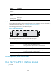
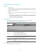
Figure 115 FIC-2E1 panel
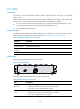
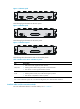
The following figure illustrates the FIC-4E1 panel.
Figure 116 FIC-4E1 panel
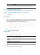
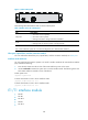
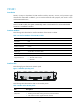
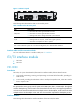
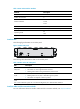
The following figure illustrates the FIC-4E1-F panel.
Figure 117 FIC-4E1-F panel
The following table describes the LEDs on the module panels.
Table 160 LEDs on the FIC-E1 and FIC-E1-F panels
LED Descri
p
tion
LINK/ACT
• ON means carrier signal has been received.
• Flashing means data is being received or/and transmitted.
• OFF means no carrier signal has been received.
LP/AL
• ON means the interface is in a loopback.
• Flashing means an AIS, LFA, or RAI alarm signal is present.
• OFF means no loopback or alarm is present.
Note:
AIS = Alarm indication signal; LFA = loss of frame alignment; RAI = Remote alarm indication
Interface cables and the connection methods
For more information about E1 interface cables, see "E1 interface."