
HP MSR2000/3000/4000 Router Series Interface Module Guide


113
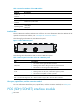
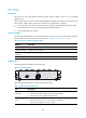
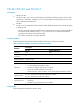
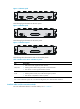
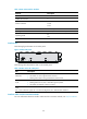
Figure 119 FIC-4T1-F panel
The following table describes the LEDs on the module panels.
Table 164 LEDs on the FIC-4T1-F panel
LED Descri
p
tion
LINK/ACT
• ON means the carrier signal has been received.
• OFF means no carrier signal has been received.
• Flashing means data is being transmitted or/and received.
LP/AL
• ON means the interface is in a loopback.
• Flashing means an AIS, LFA, or RAI alarm signal is present.
• OFF means no loopback or alarm is present.
Note:
AIS = Alarm indication signal; LFA = loss of frame alignment; RAI = Remote alarm indication
Interface cables and the connection methods
For more information about T1 interface cables, see "T1 interface."
E3/T3 interface module
• FIC-1CE3
• FIC-1CT3
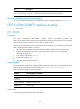
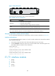
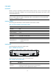
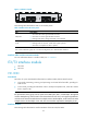
FIC-1CE3
Introduction
FIC-1CE3, the 1-port channelized E3/fractional E3 interface module, delivers these functions:
• In E3 mode, transmitting, receiving, and processing one channel of E3 fast traffic; providing E3
traffic access.
• In CE3 mode, providing the subscribers with N x 64 kbps low-speed access, where N is smaller
than or equal to 128.
NOTE:
E3 represents the tertiary group rate of E system in the TDM system, that is, 34.368 Mbps. Throu
g
h E23
and E12 demultiplexin
g
, an E3 channel can be channelized into 16 E1 lines, each supportin
g
both the E1
and CE1 modes. E23 means either E2-to-E3 multiplex or E3-to-E2 demultiplex, and E12 means E1-to-E2
multiplex or E2-to-E1 demultiplex. "E23" and "E12" discussed here represent the demultiplex process.
Interface attributes
The following table describes the interface attributes of the FIC-1CE3/FIC-2CE3.