
HP MSR2000/3000/4000 Router Series Interface Module Guide


6
Table 7 Interface Attributes of the SIC-1GEC
Attribute Description
Connector RJ-45
Interface type MDI
Frame format
• Ethernet_II
• Ethernet_SNAP
• IEEE 802.2
• IEEE 802.3
Operation mode
10/100/1000 Mbps autosensing
Full/half duplex
NOTE:
SIC-1GEC uses COMBO interface; it cannot support fiber and electrical interfaces at the same time. When
the router is powered on, the electrical interface takes effect by default. To use a fiber interface, confi
g
ure
it at the command line interface (CLI).
Interface LEDs
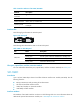
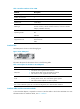
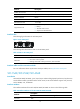
The following figure illustrates the SIC-1GEC panel.
Figure 7 SIC-1GEC panel
The following table describes the electrical interface LEDs on the left of the SIC-1GEC panel.
Table 8 LEDs for the electrical interface on the left of the SIC-1GEC panel
LED Descri
p
tion
LINK
• ON means carrier signal is received.
• OFF means no carrier signal is received.
• Green: Data is being received and transmitted at a speed of 1000 Mbps.
• Yellow: Data is being received and transmitted at a speed of 100/10 Mbps.
ACT
• OFF: No data is being received and transmitted.
• Flashing: Data is being received and transmitted.
Table 9 LEDs for the fiber interface on the right of the SIC-1GEC panel
LED Descri
p
tion
LINK
• ON means carrier signal is received.
• OFF means no carrier signal is received.
• Green: Data is being received and transmitted at a speed of 1000 Mbps.
• Yellow: Fault.
ACT
• OFF: No data is being received and transmitted.
• Flashing: Data is being received and transmitted.