
HP MSR2000/3000/4000 Router Series Interface Module Guide


118
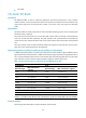
Jumper settings & description Default
Interface 2
S6
• To use a 100-ohm matched resistance for data transmission,
place the jumper over pins 1 and 2.
• To do otherwise, place the jumper over jump pins 2 and 3.
• See Figure 122.
S5
• To use a 100-ohm matched resistance for data receiving, place
the jumper over jump pins 1 and 2.
• To do otherwise, place the jumper over jump pins 2 and 3.
• See Figure 122.
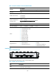
Interface 3
S8
• To use a 100-ohm matched resistance for data transmission,
place the jumper over pins 1 and 2.
• To do otherwise, place the jumper over jump pins 2 and 3.
• See Figure 122.
S7
• To use a 100-ohm matched resistance for data receiving, place
the jumper over jump pins 1 and 2.
• To do otherwise, place the jumper over jump pins 2 and 3.
• See Figure 122.
Interface LEDs
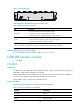
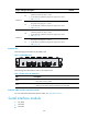
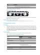
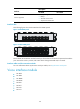
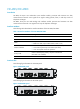
The following figure illustrates the FIC-4BSE panel.
Figure 123 FIC-4BSE panel
The following table describes the LEDs on the module panel.
Table 171 LEDs on the FIC-4BSE panel
LED Descri
p
tion
LINK
• OFF means no link is present.
• ON means a link is present.
ACT
• OFF means no data is being received or transmitted.
• Flashing means data is being received and/or transmitted.
Interface cables and the connection methods
For more information about BSE interface cables, see "BSV/BSE interface."
Serial interface module
• FIC-4SAE
• FIC-8SAE
• FIC-8ASE