
HP MSR2000/3000/4000 Router Series Interface Module Guide


8
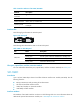
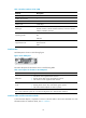
Figure 8 SIC-1E1-F panel
The status description for the LEDs is shown in the following table:
Table 11 Description for the LEDs on SIC-1E1-F panel
LED Descri
p
tion
LINK/ACT
• ON means carrier signal has been received.
• Flashing means data is being transmitted or received.
• OFF means no carrier signal has been received.
LP/AL
• ON means the interface is in a loopback.
• Flashing means an AIS, LFA, or RAI alarm signal is present.
• OFF means neither loopback nor alarm is present.
Note:
AIS = Alarm indication signal; LFA = loss of frame alignment; RAI = Remote alarm indication
Interface cables and the connection methods
For more information about E1 interface cables, see "E1 interface."
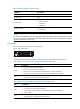
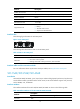
SIC-2E1-F
Introduction
2-port fractional E1 interface module (SIC-2E1-F), where F indicates fractional. The SIC-2E1-F supports:
• Transmission/Receiving and handling of E1 data streams
• CE1 (channelized E1) access
• Remote loopback and local loopback functions, facilitating fault test and location.
The FE1 operating mode supported by the SIC-2E1-F module allows only one bundle. The time slots can
only be bundled into one n x 64 kbps channel, where n is in the range of 1 to 31.
The SIC-2E1-F does not support the PRI mode.
Interface attributes
The interface attributes of SIC-2E1-F are shown in the following table:
Table 12 Interface attributes of SIC-2E1-F
Attribute Description
Connector type
D15
Number of connectors
1
Interface standard
G.703, G.704
Interface rate
2.048 Mbps
Cable type
75-ohm unbalanced coaxial cable (D15 to BNC)