
HP MSR2000/3000/4000 Router Series Interface Module Guide


9
Attribute Description
Operating modes
E1
CE1
Supported services
Backup
Terminal access
Interface LEDs
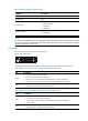
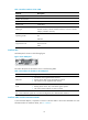
SIC-2E1-F panel is shown in the following figure:
Figure 9 SIC-2E1-F panel
The status description for the LEDs is shown in the following table:
Table 13 Description for the LEDs on SIC-2E1-F panel
LED Descri
p
tion
LINK/ACT
• ON means carrier signal has been received.
• Flashing means data is being transmitted or received.
• OFF means no carrier signal has been received.
LP/AL
• ON means the interface is in a loopback.
• Flashing means an AIS, LFA, or RAI alarm signal is present.
• OFF means neither loopback nor alarm is present.
Note:
AIS = Alarm indication signal; LFA = loss of frame alignment; RAI = Remote alarm indication
Interface cables and the connection methods
For more information about E1 interface cables, see "E1 interface."
SIC-1EPRI
Introduction
1-port E1/CE1/PRI SIC interface module (SIC-1EPRI) supports:
• Transmission/Receiving and handling of E1 data streams
• CE1 (channelized E1) access
• ISDN PRI
• Remote loopback and local loopback functions, facilitating fault test and location
• Multiple purposes through different configurations
Interface attributes
The interface attributes of SIC-1EPRI are shown in the following table: