
HP MSR2000/3000/4000 Router Series Interface Module Guide


161
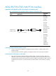
Table 211 Pinouts of E&M interface cable (Bell V 4-wire)
E&M interface
RJ-45 Pin Signal Signal direction
1 — —
2 E IN
3 RING0 IN
4 RING1 OUT
5 TIP1 OUT
6 TIP0 IN
7 M OUT
8 SG Ground
NOTE:
Because the 4E&M modules cannot determine the interface types (Bell I/II/III/V), cable types (2-wire or
4
-wire), and pinouts (E/M/Tx/Rx) of the peer switch, you must prepare the interface cables of the 4E&M
modules according to the on-site conditions. To ensure the EMC of the router, install a ferrite core near the
connector of the E&M module interface cable at the router side.
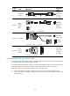
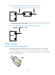
The connection method
1. Connect one end of the magnetic-core telephone cable to the RJ11 or RJ45 interface of the
interface module.
2. Connect the other end of the magnetic-core telephone cable to the remote device interface.