
HP MSR2000/3000/4000 Router Series Interface Module Guide


21
Attribute Description
Supported services
• ISDN
• ISDN supplementary services
• Multi-subscriber number
• Sub-address
• Backup
Interface LEDs
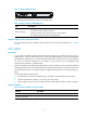
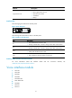
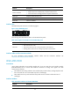
The following figures illustrate the SIC-1BS panel.
Figure 18 SIC-1BS panel
The following table describes the LEDs on SIC-1BS panel.
Table 31 LEDs on SIC-1BS panel.
LED Descri
p
tion
B1
• OFF indicates the B1 channel is idle.
• Flashing indicates the B1 channel is being used for data communication.
B2
• OFF indicates the B2 channel is idle.
• Flashing indicates the B1 channel is being used for data communication.
ACT
• OFF indicates the inactive state.
• Steady ON indicates the active state.
ON
• OFF indicates the interface module is powered off.
• ON indicates the interface module is powered on.
Interface cables and the connection methods
For more information about BS interface cables and the connection methods, see
"ADSL/BS/FXS/FXO/AM/FCM interface."
Voice interface module
• SIC-1FXS
• SIC-1FXO
• SIC-2FXS
• SIC-2FXO
• SIC-2FXS1FXO
• DSIC-4FXS1FXO
• SIC-2BSV
• SIC-1VE1
• SIC-1VT1