
HP MSR2000/3000/4000 Router Series Interface Module Guide


42
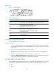
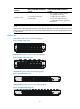
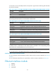
On the panel, each 10/100 Mbps interface corresponds to a green LED. The following table describes
the status of these LEDs.
Table 57 Description for the MIM-16FSW/MIM-16FSW-PoE/DMIM-24FSW/DMIM-24FSW-PoE FE LEDs
LED status Descri
p
tion
Steady green A link is present, but no data is being transmitted and received.
OFF No link is present.
Flashing green A link is present and data is being transmitted and received (ACT).
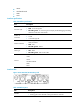
The following tables describe the GE and SFP fiber interface LEDs:
Table 58 Description for the DMIM-24FSW/DMIM-24FSW-PoE GE interface LEDs
LED status Descri
p
tion
OFF No link is present.
Steady green A gigabit link is present, but no data is being transmitted and received.
Flashing green A gigabit link is present and data is being transmitted and received (ACT).
Steady yellow A 100 Mbps link is present, but no data is being transmitted and received.
Flashing yellow A 100 Mbps link is present and data is being transmitted and received (ACT).
Table 59 Description for the DMIM-24FSW/DMIM-24FSW-PoE fiber interface LEDs
LED status Descri
p
tion
OFF No link is present.
Steady green A link is present, but no data is being transmitted and received.
Flashing green A link is present and data is being transmitted and received (ACT).
Steady yellow Error prompt
In addition, there is a POE LED on each board, which is provided for the corresponding boards
(MIM-16FSW-PoE and DMIM-24FSW-PoE) with the PoE function.
NOTE:
The two GE interfaces on the DMIM-24FSW-PoE do not support the PoE function.
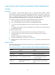
Interface cables and the connection methods
For more information about the Ethernet interface cables and the connection methods, see "Ethernet
interface."
For more information about fiber ports, optical fibers, and the connection methods, see "Fiber port."
Ethernet interface module
• MIM-2FE
• MIM-4FE
• MIM-2GBE