
HP MSR2000/3000/4000 Router Series Interface Module Guide

47
Attribute Description
Cable type 75-ohm 8E1 conversion cable
Max transmission
distance
500 m (1640.4 ft)
Operating mode ATM E1 independent link/IMA bundle mode
Supported service
AAL5 (ATM adaptation layer 5)
Protocol PPPoA, PPPoEoA, IPoA, IPoEoA
Service type CBR/VBR-rt/VBR-nrt/UBR
Interface LEDs
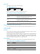
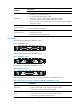
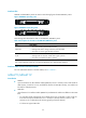
The following figures illustrate the MIM-IMA-8E1 panels.
Figure 43 MIM-IMA-8E1 (75-ohm) panel
The following table describes these LEDs on the IMA-8E1 panel.
Table 67 Description for the LEDs on the IMA-8E1 panel
LED Descri
p
tion
LINK/ACT
• ON means carrier signal has been received.
• Flashing means data is being received or/and transmitted.
• OFF means no carrier signal has been received.
LP/AL
• ON means the interface is in a loopback.
• Flashing means an AIS, LFA, or RAI alarm signal is present.
• OFF means no loopback or alarm is present.
Note:
AIS = Alarm indication signal; LFA = loss of frame alignment; RAI = Remote alarm indication
Interface cables and the connection methods
For more information about E1 interface cables, see "E1 interface."
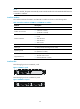
MIM-IMA-4T1
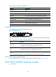
Introduction
The 4-port ATM inverse multiplexing interface module (MIM-IMA-4T1) provides four/eight T1 interfaces
that support the IMA technology. Their network application is similar to that of the
MIM-IMA-4E1/MIM-IMA-8E1 module.
Interface attributes
The following table describes the interface attributes of the MIM-IMA-4T1 module.