
HP MSR2000/3000/4000 Router Series Interface Module Guide

51
Attribute
Descri
p
tion
MIM-2E1 module
MIM-4E1/4E1-F module
Cable type
• E1 75-ohm unbalanced coaxial cable
• E1 120-ohm balanced twisted pair cable
• 120-ohm 4E1 conversion cable (MIM-4E1/MIM-4E1-F modules)
• 75-ohm 4E1 conversion cable (MIM-4E1/MIM-4E1-F modules)
• Coaxial connector, network interface connector and 75-ohm to 120-ohm adapter
(with BNC connector)
Operating mode
E1, CE1, ISDN PRI (only supported by MIM-2E1/MIM-4E1)
FE1 (only supported by MIM-4E1-F)
Supported service
• Backup
• Terminal access service
• ISDN PRI (only supported by MIM-4E1)
Interface LEDs
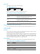
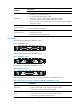
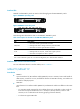
The following figure illustrates a MIM-2E1 panel.
Figure 46 MIM-2E1 panel
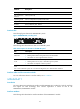
The following figure illustrates a MIM-4E1 module.
Figure 47 MIM-4E1 panel
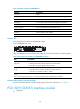
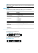
The following figure illustrates a MIM-4E1-F module.
Figure 48 MIM-4E1-F panel
The following table describes the LEDs on MIM-2E1/MIM-4E1 and MIM-4E1-F panels:
Table 73 Description for the LEDs on MIM-2E1/MIM-4E1 and MIM-4E1-F panels
LED Descri
p
tion
LINK/ACT
• ON means carrier signal has been received.
• Flashing means data is being received or/and transmitted.
• OFF means no carrier signal has been received.
LP/AL
• ON means the interface is in a loopback.
• Flashing means an AIS, LFA, or RAI alarm signal is present.
• OFF means no loopback or alarm is present.