
HP MSR2000/3000/4000 Router Series Interface Module Guide

53
Interface LEDs
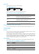
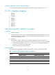
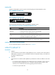
MIM-8E1 and MIM-8E1-F panels are similar. The following figures illustrate MIM-8E1 panels.
Figure 49 MIM-8E1 (75-ohm) panel
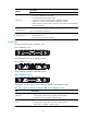
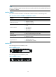
Figure 50 MIM-8E1-F (75-ohm) panel
The following table describes the LEDs on the MIM-8E1/MIM-8E1-F panel:
Table 75 Description for the LEDs on the MIM-8E1/MIM-8E1-F panel
LED Descri
p
tion
LINK/ACT
• ON means carrier signal has been received.
• Flashing means data is being received or/and transmitted.
• OFF means no carrier signal has been received.
LP/AL
• ON means the interface is in a loopback.
• Flashing means an AIS, LFA, or RAI alarm signal is present.
• OFF means no loopback or alarm is present.
Note:
AIS = Alarm indication signal; LFA = loss of frame alignment; RAI = Remote alarm indication
Interface cables and the connection methods
For more information about E1 interface cables, see "E1 interface."
MIM-2T1/MIM-4T1-F
Introduction
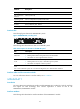
• MIM-2T1
2-port channelized T1/PRI interface module (MIM-2T1) serves to transmit/receive and handle T1
data streams, provide CT1 access, and fulfill the function of ISDN PRI. Thereby, one module can
be used for multiple purposes.
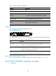
• MIM-4T1-F
4-port fractional T1 interface module (MIM-4T1-F) and MIM-2T1 module are different in the sense
that:
{ FT1 operating mode supported by T1-F modules allows only one bundle. In other words, the
time slots can only be bundled into one n x 64 kbps or 56 kbps channel, where n=1-24.
However, a CT1 module allows of arbitrary grouping of the 24 channels;
{ T1-F does not support PRI mode.