HP MSR2000/3000/4000 Router Series IP Multicast Configuration Guide (V7) Part number: 5998-3993 Software version: CMW710-R0007P02 Document version: 6PW100-20130927
Legal and notice information © Copyright 2013 Hewlett-Packard Development Company, L.P. No part of this documentation may be reproduced or transmitted in any form or by any means without prior written consent of Hewlett-Packard Development Company, L.P. The information contained herein is subject to change without notice.
Contents Multicast overview ······················································································································································· 1 Introduction to multicast ···················································································································································· 1 Information transmission techniques ·····················································································································
Configuring multicast routing and forwarding ············································································································ 36 Configuring static multicast routes ······················································································································· 36 Configuring the RPF route selection rule ············································································································· 37 Configuring multicast load splitting ·····
Configuration prerequisites ·································································································································· 73 Enabling PIM-SM ··················································································································································· 73 Configuring an RP ················································································································································· 74 Configuring a BS
MLD configuration task list ·········································································································································· 114 Configuring basic MLD functions ······························································································································· 114 Enabling MLD ······················································································································································ 115 Specifyin
IPv6 PIM configuration examples ······························································································································· 149 IPv6 PIM-DM configuration example ················································································································· 149 IPv6 PIM-SM non-scoped zone configuration example ··················································································· 152 IPv6 PIM-SM admin-scoped zone configuration example ······
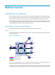
Multicast overview Introduction to multicast As a technique that coexists with unicast and broadcast, the multicast technique effectively addresses the issue of point-to-multipoint data transmission. By enabling high-efficiency point-to-multipoint data transmission over a network, multicast greatly saves network bandwidth and reduces network load.
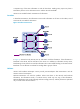
a separate copy of the same information to each of these hosts. Sending many copies can place a tremendous pressure on the information source and the network bandwidth. Unicast is not suitable for batch transmission of information. Broadcast In broadcast transmission, the information source sends information to all hosts on the subnet, even if some hosts do not need the information. Figure 2 Broadcast transmission In Figure 2, assume that only Host B, Host D, and Host E need the information.
Figure 3 Multicast transmission The multicast source sends only one copy of the information to a multicast group. Host B, Host D, and Host E, which are information receivers, must join the multicast group. The routers on the network duplicate and forward the information based on the distribution of the group members. Finally, the information is correctly delivered to Host B, Host D, and Host E.
For a better understanding of the multicast concept, you can compare multicast transmission to the transmission of TV programs. Table 1 Comparing TV program transmission and multicast transmission TV program transmission Multicast transmission A TV station transmits a TV program through a channel. A multicast source sends multicast data to a multicast group. A user tunes the TV set to the channel. A receiver joins the multicast group.
Multicast models Based on how the receivers treat the multicast sources, the multicast models include any-source multicast (ASM), source-filtered multicast (SFM), and source-specific multicast (SSM). ASM model In the ASM model, any sender can send information to a multicast group as a multicast source, and receivers can join a multicast group identified by a group address and get multicast information addressed to that multicast group.
Multicast addresses IP multicast addresses • IPv4 multicast addresses: IANA assigns the Class D address block (224.0.0.0 to 239.255.255.255) to IPv4 multicast. Table 2 Class D IP address blocks and description Address block Description 224.0.0.0 to 224.0.0.255 Reserved permanent group addresses. The IP address 224.0.0.0 is reserved. Other IP addresses can be used by routing protocols and for topology searching, and protocol maintenance. Table 3 lists common permanent group addresses.
Address Description 224.0.0.14 RSVP encapsulation. 224.0.0.15 All Core-Based Tree (CBT) routers. 224.0.0.16 Designated SBM. 224.0.0.17 All SBMs. 224.0.0.18 VRRP. IPv6 multicast addresses: • Figure 4 IPv6 multicast address format The following describes the fields of an IPv6 multicast address: { 0xFF—The most significant eight bits are 11111111. This address is an IPv6 multicast address. { Flags—The Flags field contains four bits.
Table 5 Values of the Scope field Value Meaning 0, F Reserved. 1 Interface-local scope. 2 Link-local scope. 3 Subnet-local scope. 4 Admin-local scope. 5 Site-local scope. 6, 7, 9 through D Unassigned. 8 Organization-local scope. E Global scope. { Group ID—The Group ID field contains 112 bits. It uniquely identifies an IPv6 multicast group in the scope that the Scope field defines.
Figure 7 An example of IPv6-to-MAC address mapping IMPORTANT: Because of the duplicate mapping from multicast IP address to multicast MAC address, the device might inadvertently send multicast protocol packets as multicast data in Layer 2 forwarding. To avoid this, do not use the IP multicast addresses that are mapped to multicast MAC addresses 0100-5E00-00xx and 3333-0000-00xx (where "x" specifies any hexadecimal number from 0 to F).
Figure 8 Positions of Layer 3 multicast protocols • Multicast group management protocols: Typically, the Internet Group Management Protocol (IGMP) or Multicast Listener Discovery (MLD) protocol is used between hosts and Layer 3 multicast devices that directly connect to the hosts to define how to establish and maintain their multicast group memberships.
Figure 9 Positions of Layer 2 multicast protocols • IGMP snooping and MLD snooping: IGMP snooping and MLD snooping are multicast constraining mechanisms that run on Layer 2 devices. They generate Layer 2 multicast forwarding tables by listening to IGMP or MLD messages exchanged between the hosts and Layer 3 multicast devices, and manage and control multicast data forwarding on demand in Layer 2 networks. • PIM snooping and IPv6 PIM snooping: PIM snooping and IPv6 PIM snooping run on Layer 2 devices.
incoming interface. The RPF check result determines whether the packet will be forwarded or discarded. The RPF check mechanism is the basis for most multicast routing protocols to implement multicast forwarding. For more information about the RPF mechanism, see "Configuring multicast routing and forwarding" and "Configuring IPv6 multicast routing and forwarding." Multicast support for VPNs Multicast support for VPNs refers to multicast applied in VPNs.
Multicast application in VPNs A PE device that supports multicast for VPNs does the following operations: • Maintains an independent set of multicast forwarding mechanisms for each VPN, including the multicast protocols, PIM neighbor information, and multicast routing table. In a VPN, the device forwards multicast data based on the forwarding table or routing table for that VPN. • Implements the isolation between different VPNs.
Configuring IGMP snooping Feature and hardware compatibility IGMP snooping is available only on the MSR series routers with Ethernet Layer 2 switching interface modules. For information about the Ethernet Layer 2 switching interface modules, see HP MSR Router Series Interface Module Guide. The term "switch" in this document refers to the MSR series routers with Ethernet Layer 2 switching interface modules.
Basic IGMP snooping concepts IGMP snooping related ports As shown in Figure 12, IGMP snooping runs on Switch A and Switch B, and Host A and Host C are receivers in a multicast group. Figure 12 IGMP snooping related ports The following describes the ports involved in IGMP snooping: • Router port—Layer 3 multicast device-side port. Layer 3 multicast devices include designated routers (DRs) and IGMP queriers. In Figure 12, Ethernet 1/1 of Switch A and Ethernet 1/1 of Switch B are the router ports.
Aging timers for dynamic ports in IGMP snooping Timer Description Message received before the timer expires Action after the timer expires Dynamic router port aging timer. When a port recieves an IGMP general query with the source address other than 0.0.0.0 or PIM hello message, the switch starts or resets an aging timer for it. When the timer expires, the dynamic router port ages out. IGMP general query with the source address other than 0.0.0.0 or PIM hello message.
• If a forwarding entry matches the group address, but the receiving port is not in the forwarding entry for the group, the switch adds the port as a dynamic member port to the forwarding entry, and starts an aging timer for the port. • If a forwarding entry matches the group address and the receiving port is in the forwarding entry for the group, the switch restarts the aging timer for the port.
Protocols and standards RFC 4541, Considerations for Internet Group Management Protocol (IGMP) and Multicast Listener Discovery (MLD) Snooping Switches IGMP snooping configuration task list Task at a glance Configuring basic IGMP snooping functions • • • • (Required.) Enabling IGMP snooping (Optional.) Specifying the IGMP snooping version (Optional.) Setting the maximum number of IGMP snooping forwarding entries (Optional.
Step Command Remarks Enable IGMP snooping globally and enter IGMP-snooping view. igmp-snooping By default, IGMP snooping is disabled. 3. Return to system view. quit N/A 4. Enable IGMP snooping for specified VLANs. enable vlan vlan-list By default, IGMP snooping is disabled for a VLAN. 2. To enable IGMP snooping for a VLAN in VLAN view: Step Command Remarks 1. Enter system view. system-view N/A 2. Enable IGMP snooping globally and enter IGMP-snooping view.
To specify the IGMP snooping version for a VLAN in VLAN view: Step Command Remarks 1. Enter system view. system-view N/A 2. Enter VLAN view. vlan vlan-id N/A 3. Specify the version of IGMP snooping. igmp-snooping version version-number The default setting is IGMPv2 snooping. Setting the maximum number of IGMP snooping forwarding entries You can modify the maximum number of IGMP snooping forwarding entries.
Step Command Remarks 2. Enter IGMP-snooping view. igmp-snooping N/A 3. Set the maximum response time for IGMP general queries. max-response-time interval The default setting is 10 seconds. Set the IGMP last-member query interval. last-member-query-interval interval The default setting is 1 second. 4. Configuring parameters for IGMP queries and responses in a VLAN Step Command Remarks 1. Enter system view. system-view N/A 2. Enter VLAN view. vlan vlan-id N/A 3.
Step Command Remarks 2. Enter IGMP-snooping view. igmp-snooping N/A 3. Set the aging timer for dynamic router ports globally. router-aging-time interval The default setting is 260 seconds. 4. Set the global aging timer for dynamic member ports globally. host-aging-time interval The default setting is 260 seconds. Setting the aging timers for the dynamic ports in a VLAN Step Command Remarks 1. Enter system view. system-view N/A 2. Enter VLAN view. vlan vlan-id N/A 3.
Enabling IGMP snooping fast-leave processing The IGMP snooping fast-leave processing feature enables the switch to process IGMP leave messages quickly. When a port that is enabled with the IGMP snooping fast-leave processing feature receives an IGMP leave message, the switch immediately removes that port from the forwarding entry for the multicast group specified in the message. Then, when the switch receives IGMP group-specific queries for that multicast group, it does not forward them to that port.
• This configuration takes effect on the multicast groups that a port dynamically joins. If you configure the port as a static member port for a multicast group, this configuration does not take effect on the multicast group. • You can configure a multicast filter either for the current port in proper interface view or globally for all ports in IGMP-snooping view. If the configurations are made in both interface view and IGMP-snooping view, the configuration made in interface view takes priority.
Enabling the multicast group replacement function When the number of multicast groups on a switch or a port exceeds the limit: • If the multicast group replacement is enabled, the switch or the port replaces an existing multicast group with a newly joined multicast group. • If the multicast group replacement is disabled, the switch or the port discards IGMP reports that are used for joining a new multicast group.
Task Command Display information about dynamic IGMP snooping forwarding entries (MSR2000/MSR3000). display igmp-snooping group [ group-address | source-address ] * [ vlan vlan-id ] [ verbose ] Display information about dynamic IGMP snooping forwarding entries (MSR4000). display igmp-snooping group [ group-address | source-address ] * [ vlan vlan-id ] [ verbose ] [ slot slot-number ] Display information about static IGMP snooping forwarding entries (MSR2000/MSR3000).
Static port configuration example Network requirements As shown in Figure 13, Router A runs IGMPv2 and serves as the IGMP querier. Switch A, Switch B, and Switch C run IGMPv2 snooping. Host A and host C are permanent receivers of multicast group 224.1.1.1. Configure Ethernet 1/3 and Ethernet 1/5 on Switch C as static member ports for multicast group 224.1.1.1 to enhance the reliability of multicast traffic transmission. Suppose the STP runs on the network.
Configuration procedure 1. Assign an IP address and subnet mask to each interface as shown in Figure 13. (Details not shown.) 2. On Router A, enable IP multicast routing globally, enable IGMP on Ethernet 1/1, and enable PIM-DM on each interface.
[SwitchC-igmp-snooping] quit # Create VLAN 100, assign Ethernet 1/1 through Ethernet 1/5 to the VLAN, and enable IGMP snooping for the VLAN. [SwitchC] vlan 100 [SwitchC-vlan100] port ethernet 1/1 to ethernet 1/5 [SwitchC-vlan100] igmp-snooping enable [SwitchC-vlan100] quit # Configure Ethernet 1/3 and Ethernet 1/5 as static member ports for multicast group 224.1.1.1. [SwitchC] interface Ethernet 1/3 [SwitchC-Ethernet1/3] igmp-snooping static-group 224.1.1.
Troubleshooting IGMP snooping Layer 2 multicast forwarding cannot function Symptom Layer 2 multicast forwarding cannot function on the switch. Analysis IGMP snooping is not enabled. Solution 1. Use the display igmp-snooping command to display IGMP snooping status. 2. If IGMP snooping is not enabled, use the igmp-snooping command in system view to enable IGMP snooping globally, and then use the igmp-snooping enable command in VLAN view to enable IGMP snooping for the VLAN. 3.
Configuring multicast routing and forwarding Overview The following tables are involved in multicast routing and forwarding: • Multicast routing table of each multicast routing protocol, such as the PIM routing table. • General multicast routing table that summarizes multicast routing information generated by different multicast routing protocols. The multicast routing information from multicast sources to multicast groups are stored in a set of (S, G) routing entries.
For more information about the route preference, see Layer 3—IP Routing Configuration Guide. { If the router does not use the longest prefix match principle, the router selects the route that has the higher priority as the RPF route. If the routes have the same priority, the static multicast route takes precedence over the unicast route..
Figure 14 RPF check process IP Routing Table on Router C Destination/Mask Interface 192.168.0.0/24 Eth1/2 Router B Receiver Eth1/1 Source 192.168.0.1/24 Router A Eth1/2 Multicast packets Eth1/1 Receiver Router C As shown in Figure 14, assume that unicast routes are available in the network, and no static multicast routes have been configured on Router C. Multicast packets travel along the SPT from the multicast source to the receivers.
Figure 15 Changing an RPF route As shown in Figure 15, when no static multicast route is configured, Router C's RPF neighbor on the path back to the source is Router A, and the multicast data from the source travels through Router A to Router C. When a static multicast route is configured on Router C with Router B as its RPF neighbor on the path back to the source, the multicast data from the source travels along the path: Router A to Router B and then to Router C.
and Router D, specifying Router B as the RPF neighbor of Router C and Router C as the RPF neighbor of Router D, the receiver hosts can receive the multicast data from the multicast source. NOTE: A static multicast route is effective only on the multicast router on which it is configured, and will not be advertised throughout the network or redistributed to other routers.
NOTE: The device can route and forward multicast data only through the primary IP addresses of interfaces, rather than their secondary addresses or unnumbered IP addresses. For more information about primary and secondary IP addresses, and IP unnumbered, see Layer 3—IP Services Configuration Guide. Enabling IP multicast routing Enable IP multicast routing before you configure any Layer 3 multicast functionality on the public network or VPN instance.
Configuring the RPF route selection rule You can configure the router to select the RPF route based on the longest prefix match principle. For more information about RPF route selection, see "RPF check process." To configure a multicast routing policy: Step Command Remarks 1. Enter system view. system-view N/A 2. Enter MRIB view. multicast routing [ vpn-instance vpn-instance-name ] N/A 3. Configure the device to select the RPF route based on the longest prefix match.
Step 3. Configure a multicast forwarding boundary. Command Remarks multicast boundary group-address { mask-length | mask } By default, no forwarding boundary is configured. Configuring static multicast MAC address entries This feature is available only on the MSR series routers with Ethernet Layer 2 switching interface modules. For information about the Ethernet Layer 2 switching interface modules, see HP MSR Router Series Interface Module Guide.
Displaying and maintaining multicast routing and forwarding CAUTION: The reset commands might cause multicast data transmission failures. Execute display commands in any view and reset commands in user view. Task Command Display information about static multicast MAC address table. display mac-address [ mac-address [ vlan vlan-id ] | [ multicast ] [ vlan vlan-id ] [ count ] ] Display information about the interfaces maintained by the MRIB.
Task Command Clear forwarding entries from the multicast forwarding table. reset multicast [ vpn-instance vpn-instance-name ] forwarding-table { { source-address [ mask { mask-length | mask } ] | group-address [ mask { mask-length | mask } ] | incoming-interface { interface-type interface-number } } * | all } Clear routing entries from the multicast routing table.
Configuration procedure 1. Configure the IP address and subnet mask for each interface as shown in Figure 18. (Details not shown.) 2. Enable OSPF on the routers in the PIM-DM domain to make sure the network-layer on the PIM-DM network is interoperable and the routing information among the routers can be dynamically updated. (Details not shown.) 3.
4. Configure a static multicast route on Router B, specifying Router C as its RPF neighbor to the source. [RouterB] ip rpf-route-static 50.1.1.100 24 20.1.1.2 Verifying the configuration # Use the display multicast rpf-info command on Router B to display information about the RPF route to the source. [RouterB] display multicast rpf-info 50.1.1.100 RPF information about source 50.1.1.100: RPF interface: Ethernet1/2, RPF neighbor: 20.1.1.2 Referenced route/mask: 50.1.1.
2. Enable OSPF on Router B and Router C to make sure the network-layer on the PIM-DM network is interoperable and the routing information among the routers can be dynamically updated. (Details not shown.) 3. Enable IP multicast routing, and enable IGMP and PIM-DM: # On Router C, enable IP multicast routing globally, enable IGMP on Ethernet 1/1, and enable PIM-DM on each interface.
Referenced route/mask: 50.1.1.0/24 Referenced route type: multicast static Route selection rule: preference-preferred Load splitting rule: disable [RouterC] display multicast rpf-info 50.1.1.100 RPF information about source 50.1.1.100: RPF interface: Ethernet1/2, RPF neighbor: 20.1.1.2 Referenced route/mask: 50.1.1.
[RouterA-Tunnel0] source 20.1.1.1 [RouterA-Tunnel0] destination 30.1.1.2 [RouterA-Tunnel0] quit # Create interface Tunnel 0 on Router C and specify the tunnel encapsulation mode as GRE over IPv4. system-view [RouterC] interface tunnel 0 mode gre # Configure the IP address for interface Tunnel 0 and specify its source and destination addresses. [RouterC-Tunnel0] ip address 50.1.1.2 24 [RouterC-Tunnel0] source 30.1.1.2 [RouterC-Tunnel0] destination 20.1.1.1 [RouterC-Tunnel0] quit 4.
# Display PIM routing table information on Router C. [RouterC] display pim routing-table Total 1 (*, G) entry; 1 (S, G) entry (*, 225.1.1.1) Protocol: pim-dm, Flag: WC UpTime: 00:04:25 Upstream interface: NULL Upstream neighbor: NULL RPF prime neighbor: NULL Downstream interface(s) information: Total number of downstreams: 1 1: Ethernet1/1 Protocol: igmp, UpTime: 00:04:25, Expires: never (10.1.1.100, 225.1.1.1) Protocol: pim-dm, Flag: ACT UpTime: 00:06:14 Upstream interface: Tunnel0 Upstream neighbor: 50.
Configuring IGMP Overview Internet Group Management Protocol (IGMP) establishes and maintains the multicast group memberships between a Layer 3 multicast device and its directly connected hosts. IGMP has three versions: • IGMPv1 (defined by RFC 1112) • IGMPv2 (defined by RFC 2236) • IGMPv3 (defined by RFC 3376) All IGMP versions support the ASM model. In addition to the ASM model, IGMPv3 can directly implement the SSM model.
Figure 21 IGMP queries and reports IP network DR Router A Router B Ethernet Host A (G2) Host B (G1) Host C (G1) Query Report As shown in Figure 21, Host B and Host C are interested in the multicast data addressed to the multicast group G1, and Host A is interested in the multicast data addressed to G2. The following process describes how the hosts join the multicast groups and how the IGMP querier (Router B in Figure 21) maintains the multicast group memberships: 1.
IGMPv2 enhancements Backwards-compatible with IGMPv1, IGMPv2 has introduced a querier election mechanism and a leave-group mechanism. Querier election mechanism In IGMPv1, the DR elected by the Layer 3 multicast routing protocol (such as PIM) serves as the querier among multiple routers that run IGMP on the same subnet. IGMPv2 introduced an independent querier election mechanism. The querier election process is as follows: 1.
• If the host expects to receive multicast data from specific sources like S1, S2, …, it sends a report with the Filter-Mode denoted as "Include Sources (S1, S2, …)." • If the host expects to reject multicast data from specific sources like S1, S2, …, it sends a report with the Filter-Mode denoted as "Exclude Sources (S1, S2, …)." As shown in Figure 22, the network comprises two multicast sources, Source 1 (S1) and Source 2 (S2), both of which can send multicast data to the multicast group G.
{ TO_IN—The filtering mode has changed from Exclude to Include. { TO_EX—The filtering mode has changed from Include to Exclude. { { ALLOW—The Source Address fields in this group record contain a list of the additional sources from which the system wants to obtain data for packets sent to the specified multicast address. If the change was to an Include source list, these sources are the addresses that were added to the list.
• Determine the multicast group and multicast source addresses for static group member configuration. • Determine the ACL for multicast group filtering. Enabling IGMP To configure IGMP, enable IGMP on the interface where the multicast group memberships are established and maintained. To enable IGMP: Step Command Remarks 1. Enter system view. system-view N/A 2. Enable IP multicast routing and enter MRIB view. multicast routing [ vpn-instance vpn-instance-name ] Disabled by default. 3.
A static member interface does not respond to queries that the IGMP querier sends. When you configure an interface as a static member or cancel this configuration on the interface, the interface does not send any IGMP report or IGMP leave message without a request. This is because the interface is not a real member of the multicast group or the multicast source and group. • Configuration procedure To configure an interface as a static member interface: Step Command Remarks 1. Enter system view.
Enabling IGMP fast-leave processing In some applications, such as ADSL dial-up networking, only one multicast receiver host is attached to an interface of the IGMP querier. To allow fast response to the leave messages of the host when it switches frequently from one multicast group to another, you can enable fast-leave processing on the IGMP querier.
IGMP configuration example Network requirements AS shown in Figure 23, VOD streams are sent to receiver hosts in multicast. Receiver hosts of different organizations form stub networks N1 and N2. Host A and Host C are receiver hosts in N1 and N2, respectively. IGMPv2 runs between Router A and N1, and between the other two routers and N2. Router A acts as the IGMP querier in N1. Router B acts as the IGMP querier in N2 because it has a lower IP address. The hosts in N1 can join only the multicast group 224.1.
[RouterA-Ethernet1/1] pim dm [RouterA-Ethernet1/1] quit [RouterA] interface ethernet 1/2 [RouterA-Ethernet1/2] pim dm [RouterA-Ethernet1/2] quit # On Router B, enable IP multicast routing globally, enable IGMP on Ethernet 1/1, and enable PIM-DM on each interface.
Querier for IGMP: 10.110.2.1 (This router) IGMP groups reported in total: 1 Troubleshooting IGMP No membership information on the receiver-side router Symptom When a host sends a report for joining the multicast group G, no membership information of the multicast group G exists on the router closest to that host. Analysis • The correctness of networking and interface connections and whether the protocol layer of the interface is up directly affect the generation of group membership information.
• In addition, although IGMP routers are partially compatible with hosts that separately run different versions of IGMP, all routers on the same subnet must run the same version of IGMP. Inconsistent IGMP versions running on routers on the same subnet leads to inconsistency of IGMP memberships. 1. Use the display current-configuration command to verify the IGMP information on the interfaces. 2.
Configuring PIM Overview Protocol Independent Multicast (PIM) provides IP multicast forwarding by leveraging unicast static routes or unicast routing tables generated by any unicast routing protocol, such as RIP, OSPF, IS-IS, or BGP. PIM is not dependent on any particular unicast routing protocol, and it uses the underlying unicast routing to generate a routing table with routes. PIM uses the RPF mechanism to implement multicast forwarding.
Neighbor discovery In a PIM domain, each interface that runs PIM on a router periodically multicasts PIM hello messages to all other PIM routers (identified by the address 224.0.0.13) on the local subnet to discover PIM neighbors, maintain PIM neighboring relationship with other routers, and build and maintain SPTs. SPT building The process of building an SPT is the flood-and-prune process: 1.
Graft To reduce the join latency when a new receiver on a previously pruned branch joins a multicast group, PIM-DM uses a graft mechanism to turn the pruned branch into a forwarding branch, as follows: 1. The node that needs to receive the multicast data sends a graft message to its upstream node, telling it to rejoin the SPT. 2.
PIM-SM overview PIM-DM uses the flood-and-prune cycles to build SPTs for multicast data forwarding. Although an SPT has the shortest paths from the multicast source to the receivers, it is built with a low efficiency and is not suitable for large- and medium-sized networks. PIM-SM uses the pull mode for multicast forwarding, and it is suitable for large- and medium-sized networks with sparsely and widely distributed multicast group members.
IMPORTANT: IGMP must be enabled on the device that acts as the receiver-side DR. Otherwise, the receiver hosts attached to the DR cannot join any multicast groups. Figure 26 DR election As shown in Figure 26, the DR election process is as follows: 1. The routers on the shared-media LAN send hello messages to one another. The hello messages contain the priority for DR election. The router with the highest DR priority is elected as the DR. 2.
BSR encapsulates the RP-set information in the bootstrap messages (BSMs) and floods the BSMs to the entire PIM-SM domain. Figure 27 Information exchange between C-RPs and BSR Based on the information in the RP-set, all routers in the network can select the proper RP for a specific multicast group based on the following rules: 1. The C-RP that is designated to a smaller group range wins. 2. If the group ranges are the same, the C-RP with the highest priority wins. 3.
1. When a receiver wants to join the multicast group G, it uses an IGMP message to inform the receiver-side DR. 2. After getting the receiver information, the DR sends a join message, which is forwarded hop by hop to the RP for the multicast group. 3. The routers along the path from the DR to the RP form an RPT branch. Each router on this branch adds to its forwarding table a (*, G) entry, where the asterisk (*) means any multicast source. The RP is the root of the RPT, and the DR is a leaf of the RPT.
multicast data reaches the RP along the SPT, the RP unicasts a register-stop message to the source-side DR to prevent the DR from unnecessarily encapsulating the data. Switchover to SPT CAUTION: If the router is an RP, disabling switchover to SPT might cause multicast traffic forwarding failures on the source-side DR. When disabling switchover to SPT, be sure you fully understand its impact on your network. In a PIM-SM domain, only one RP and one RPT provide services for a specific multicast group.
Administrative scoping overview Typically, a PIM-SM domain contains only one BSR, which is responsible for advertising RP-set information within the entire PIM-SM domain. The information about all multicast groups is forwarded within the network that the BSR administers. This is called the "non-scoped BSR mechanism." Administrative scoping mechanism To implement refined management, you can divide a PIM-SM domain into a global-scoped zone and multiple administratively-scoped zones (admin-scoped zones).
Figure 30 Relationship in view of geographical locations As shown in Figure 30, for the multicast groups in a specific group address range, the admin-scoped zones must be geographically separated and isolated. A router cannot belong to multiple admin-scoped zones. An admin-scoped zone contains routers that are different from other admin-scoped zones. However, the global-scoped zone includes all routers in the PIM-SM domain.
PIM-SSM overview The ASM model includes PIM-DM and PIM-SM. The SSM model can be implemented by leveraging part of the PIM-SM technique. It is also called "PIM-SSM." The SSM model provides a solution for source-specific multicast. It maintains the relationship between hosts and routers through IGMPv3. In actual applications, part of IGMPv3 and PIM-SM techniques are adopted to implement the SSM model.
After receiving a report message, the DR first checks whether the group address in this message is in the SSM group range and does the following: • If the group address is in the SSM group range, the DR sends a subscribe message hop by hop toward the multicast source S. All routers along the path from the DR to the source create an (S, G) entry so as to build an SPT, which is rooted at the multicast source S and has the receivers as its leaves. This SPT is the transmission channel in PIM-SSM.
Enabling PIM-DM Enable IP multicast routing before you configure PIM. With PIM-DM enabled on interfaces, routers can establish PIM neighbor relationship and process PIM messages from their PIM neighbors. When you deploy a PIM-DM domain, enable PIM-DM on all non-border interfaces of the routers. IMPORTANT: All the interfaces on a device must operate in the same PIM mode in the public network or the same VPN instance. To enable PIM-DM: Step Command Remarks 1. Enter system view. system-view N/A 2.
If the router receives a new state refresh message within the specified waiting time, it discards the message. If this timer times out, the router accepts a new state refresh message, refreshes its own PIM-DM state, and resets the waiting timer. The TTL value of a state refresh message decrements by 1 whenever it passes a router before it is forwarded to the downstream node until the TTL value comes down to 0. In a small network, a state refresh message might cycle in the network.
Configuring PIM-SM PIM-SM configuration task list Task at a glance (Required.) Enabling PIM-SM (Required.) Configuring an RP • Configuring a static RP • Configuring a C-RP NOTE: Perform at least one of the above tasks. In a network with a static RP, skip the task of configuring a BSR. Configuring a BSR: • (Required.) Configuring a C-BSR • (Optional.) Configuring a PIM domain border • (Optional.) Disabling the BSM semantic fragmentation function (Optional.
Step Command Remarks 3. Return to system view. quit N/A 4. Enter interface view. interface interface-type interface-number N/A 5. Enable PIM-SM. pim sm By default, PIM-SM is disabled. Configuring an RP An RP can provide services for multiple or all multicast groups. However, only one RP can forward multicast traffic for a multicast group at a moment. An RP can be manually configured or dynamically elected through the BSR mechanism.
does not receive any advertisement message when the timer expires, it regards the C-RP failed or unreachable. To guard against C-RP spoofing, you must configure a legal C-RP address range and the multicast group range to which the C-RP is designated. In addition, because every C-BSR might become the BSR, you must configure the same filtering policy on all C-BSRs in the PIM-SM domain. To configure a C-RP: Step Command Remarks 1. Enter system view. system-view N/A 2. Enter PIM view.
• Some maliciously configured hosts can forge BSMs to fool routers and change RP mappings. Such attacks often occur on border routers. Because a BSR is inside the network whereas hosts are outside the network, you can protect a BSR against attacks from external hosts by enabling the border routers to perform neighbor checks and RPF checks on BSMs and to discard unwanted messages.
Step Configure a PIM domain border. 3. Command Remarks pim bsr-boundary By default, no PIM domain border is configured. Disabling the BSM semantic fragmentation function Generally, a BSR periodically advertises the RP-set information in BSMs within the PIM-SM domain. It encapsulates a BSM in an IP datagram and might fragment the datagram if the message exceeds the MTU. In this case, loss of a single IP fragment leads to unavailability of the entire message.
To configure multicast source registration: Step Command Remarks 1. Enter system view. system-view N/A 2. Enter PIM view. pim [ vpn-instance vpn-instance-name ] N/A 3. Configure a filtering rule for register messages. register-policy acl-number By default, no register filtering rule exists. 4. Configure the device to calculate the checksum based on the entire register message. register-whole-checksum By default, the device calculates the checksum based on the header of a register message.
PIM-SSM configuration task list Task Remarks Enabling PIM-SM Required. Configuring the SSM group range Optional. Configuring common PIM features Optional. Configuration prerequisites Before you configure PIM-SSM, configure a unicast routing protocol so that all devices in the domain are interoperable at the network layer. Enabling PIM-SM The implementation of the SSM model is based on subsets of PIM-SM. Therefore, you must enable PIM-SM before configuring PIM-SSM.
When a member of a multicast group in the SSM group range sends an IGMPv1 or IGMPv2 report message, the device does not trigger a (*, G) join. • Configuration procedure To configure an SSM group range: Step Command Remarks 1. Enter system view. system-view N/A 2. Enter PIM view. pim N/A 3. Configure the SSM group range. ssm-policy acl-number The default range is 232.0.0.0/8. Configuring common PIM features Configuration task list Task at a glance (Optional.
Step Command Remarks 1. Enter system view. system-view N/A 2. Enter PIM view. pim [ vpn-instance vpn-instance-name ] N/A 3. Configure a multicast data filter: source-policy acl-number By default, no multicast data filter is configured. Configuring a hello message filter Along with the wide applications of PIM, the security requirement for the protocol is becoming increasingly demanding.
A router does not immediately prune an interface after it receives a prune message from the interface. Instead, it starts a timer (the prune message delay plus the override interval). If interface receives a join message before the override interval expires, the router does not prune the interface. Otherwise, the router prunes the interface when the timer (the prune message delay plus the override interval) expires.
Step Command Remarks 5. Set the prune delay. pim hello-option lan-delay delay By default, the prune delay is 500 milliseconds. 6. Set the override interval. pim hello-option override-interval interval By default, the override interval is 2500 milliseconds. 7. Enable the neighbor tracking function. pim hello-option neighbor-tracking By default, the neighbor tracking function is disabled. 8. Enable dropping hello messages without the Generation ID option.
Step 6. Set the multicast source lifetime. Command Remarks source-lifetime time By default, the multicast source lifetime is 210 seconds. Configuring common PIM timers on an interface Step Command Remarks 1. Enter system view. system-view N/A 2. Enter interface view. interface interface-type interface-number N/A 3. Set the interval to send hello messages. pim timer hello interval By default, the interval to send hello messages is 30 seconds. 4.
detect DR failures and start a new DR election process. For more information about BFD, see High Availability Configuration Guide. Before you configure this feature on an interface, be sure to enable PIM-DM or PIM-SM on the interface. To enable PIM to work with BFD: Step Command Remarks 1. Enter system view. system-view N/A 2. Enter interface view. interface interface-type interface-number N/A 3. Enable PIM to work with BFD. pim bfd enable By default, PIM is disabled to work with BFD.
PIM configuration examples PIM-DM configuration example Network requirements As shown in Figure 33, VOD streams are sent to receiver hosts in multicast. The receiver groups of different organizations form stub networks, and one or more receiver hosts exist in each stub network. The entire PIM domain operates in the dense mode. Host A and Host C are multicast receivers in two stub networks N1 and N2. IGMPv2 runs between Router A and N1 and between Router B, Router C, and N2.
# On Router A, enable IP multicast routing globally, enable IGMP on Ethernet 1/1, and enable PIM-DM on each interface.
Assume that Host A needs to receive the information addressed to multicast group 225.1.1.1. After the multicast source 10.110.5.100/24 sends multicast packets to the multicast group, an SPT is established through traffic flooding. Routers on the SPT path (Router A and Router D) have their (S, G) entries. Host A sends an IGMP report to Router A to join the multicast group G, and a (*, G) entry is generated on Router A.
PIM-SM non-scoped zone configuration example Network requirements As shown in Figure 34, VOD streams are sent to receiver hosts in multicast. The receivers of different subnets form stub networks, and at least one receiver host exist in each stub network. The entire PIM-SM domain contains only one BSR. Host A and Host C are multicast receivers in the stub networks N1 and N2. Ethernet 1/3 on Router D and Ethernet 1/3 on Router E act as C-BSRs and C-RPs. The C-BSR on Router E has a higher priority.
2. Enable OSPF on all routers on the PIM-SM network to make sure the network-layer on the PIM-SM network is interoperable and the routing information among the routers can be dynamically updated. (Details not shown.) 3. Enable IP multicast routing, IGMP and PIM-SM: # On Router A, enable IP multicast routing globally, enable IGMP on Ethernet 1/1, and enable PIM-SM on each interface.
[RouterA] display pim interface Interface NbrCnt HelloInt DR-Pri DR-Address Eth1/1 0 30 1 10.110.1.1 Eth1/2 1 30 1 192.168.1.2 Eth1/3 1 30 1 192.168.9.2 (local) # Display BSR information on Router A. [RouterA] display pim bsr-info Scope: non-scoped State: Accept Preferred Bootstrap timer: 00:01:44 Elected BSR address: 192.168.9.2 Priority: 20 Hash mask length: 32 Uptime: 00:40:40 # Display BSR information on Router D.
PIM-SM admin-scoped zone configuration example Network requirements As shown in Figure 35, VOD streams are sent to receiver hosts in multicast. The entire PIM-SM domain is divided into admin-scoped zone 1, admin-scoped zone 2, and the global-scoped zone. Router B, Router C, and Router D are ZBRs of the three zones, respectively. The source 1 and the source 2 send different multicast data to the multicast group 239.1.1.1.
Router C Router H Router I Eth1/4 10.110.3.1/24 Eth1/1 192.168.3.1/24 Eth1/2 Eth1/3 Eth1/4 10.110.2.2/24 Eth1/3 10.110.7.2/24 Eth1/1 10.110.9.1/24 10.110.4.1/24 Eth1/2 10.110.8.2/24 10.110.5.1/24 Eth1/3 10.110.3.2/24 Eth1/1 192.168.5.1/24 Router F Router G Eth1/5 10.110.6.1/24 Eth1/2 10.110.9.2/24 Eth1/1 10.110.10.1/24 Source 1 - 192.168.2.10/24 Eth1/2 10.110.6.2/24 Source 2 - 192.168.3.10/24 Eth1/1 192.168.6.1/24 Source 3 - 192.168.5.10/24 Eth1/2 10.110.10.
[RouterB-Ethernet1/4] quit # Enable IP multicast routing and PIM-SM on Router C, Router D, Router F, Router G, and Router H in the same way Router B is configured. (Details not shown.) 4. Configure admin-scoped zone boundaries: # On Router B, configure Ethernet 1/3 and Ethernet 1/4 as the boundaries of admin-scoped zone 1. [RouterB] interface ethernet 1/3 [RouterB-Ethernet1/3] multicast boundary 239.0.0.
[RouterF] pim [RouterF-pim] c-bsr 10.110.9.1 [RouterF-pim] c-rp 10.110.9.1 [RouterF-pim] quit Verifying the configuration # Display BSR information on Router B. [RouterB] display pim bsr-info Scope: non-scoped State: Accept Preferred Bootstrap timer: 00:01:44 Elected BSR address: 10.110.9.1 Priority: 64 Hash mask length: 30 Uptime: 00:01:45 Scope: 239.0.0.0/8 State: Elected Bootstrap timer: 00:00:06 Elected BSR address: 10.110.1.
Scope: non-scoped State: Elected Bootstrap timer: 00:00:49 Elected BSR address: 10.110.9.1 Priority: 64 Hash mask length: 30 Uptime: 00:11:11 Candidate BSR address: 10.110.9.1 Priority: 64 Hash mask length: 30 # Display RP information on Router B. [RouterB] display pim rp-info BSR RP information: Scope: non-scoped Group/MaskLen: 224.0.0.0/4 RP address Priority HoldTime Uptime Expires 10.110.9.1 192 150 00:03:39 00:01:51 RP address Priority HoldTime Uptime Expires 10.110.1.
Host A and Host C are multicast receivers in two stub networks. The SSM group range is 232.1.1.0/24. IGMPv3 runs between Router A and N1 and between Router B, Router C, and N2. Figure 36 Network diagram Receiver Host A Router A Et h1 /2 Et h1 /2 Eth1/1 Eth1/3 Host B Eth1/3 Eth1/1 Eth1/4 Receiver Eth1/3 Source Router D Eth1/1 Eth1/2 Eth1/2 Router E 10.110.5.
[RouterA-Ethernet1/1] igmp enable [RouterA-Ethernet1/1] igmp version 3 [RouterA-Ethernet1/1] pim sm [RouterA-Ethernet1/1] quit [RouterA] interface ethernet 1/2 [RouterA-Ethernet1/2] pim sm [RouterA-Ethernet1/2] quit [RouterA] interface ethernet 1/3 [RouterA-Ethernet1/3] pim sm [RouterA-Ethernet1/3] quit # Enable IP multicast routing, IGMP, and PIM-SM on Router B and Router C in the same way Router A is configured. (Details not shown.
RPF prime neighbor: 192.168.1.2 Downstream interface(s) information: Total number of downstreams: 1 1: Ethernet1/1 Protocol: igmp, UpTime: 00:13:25, Expires: 00:03:25 # Display PIM routing table information on Router D. [RouterD] display pim routing-table Total 0 (*, G) entry; 1 (S, G) entry (10.110.5.100, 232.1.1.
of the router's RPF neighbor operate in different PIM modes, the multicast distribution tree cannot be built correctly, causing abnormal multicast forwarding. • The same PIM mode must run on the entire network. Otherwise, the multicast distribution tree cannot be built correctly, causing abnormal multicast forwarding. 1. Use display ip routing-table to verify that a unicast route to the multicast source or the RP is available. 2.
Analysis • RPs are the core of a PIM-SM domain. An RP provides services for a specific multicast group, and multiple RPs can coexist on a network. Make sure the RP information on all routers is exactly the same to map a specific multicast group to the same RP. Otherwise, multicast forwarding fails. • If a static RP is configured, use the same static RP configuration on all routers on the entire network. Otherwise, multicast forwarding fails. 1.
Configuring IPv6 multicast routing and forwarding Overview IPv6 multicast routing and forwarding uses the following tables: • IPv6 multicast protocols' routing tables, such as the IPv6 PIM routing table. • General IPv6 multicast routing table that summarizes the multicast routing information generated by different IPv6 multicast routing protocols. The IPv6 multicast routing information from IPv6 multicast sources to IPv6 multicast groups are stored in a set of (S, G) routing entries.
interface of the packet as the incoming interface of the forwarding entry. After the router receives an IPv6 multicast packet, it searches its IPv6 multicast forwarding table: • If no forwarding entry matches the packet, the packet undergoes an RPF check. The router creates an IPv6 multicast routing entry with the RPF interface as the incoming interface and installs the entry into the IPv6 multicast forwarding table.
IPv6 multicast forwarding across IPv6 unicast subnets Routers forward the IPv6 multicast data from an IPv6 multicast source hop by hop along the forwarding tree, but some routers might not support IPv6 multicast protocols in a network. When the IPv6 multicast data is forwarded to a router that does not support IPv6 multicast, the forwarding path is blocked.
Step Enable IPv6 multicast routing and enter IPv6 MRIB view. 2. Command Remarks ipv6 multicast routing [ vpn-instance vpn-instance-name ] By default, IPv6 multicast routing is disabled. Configuring IPv6 multicast routing and forwarding Before you configure IPv6 multicast routing and forwarding, complete the following tasks: • Configure an IPv6 unicast routing protocol so that all devices in the domain are interoperable at the network layer. • Configure IPv6 PIM-DM or IPv6 PIM-SM.
condition for the IPv6 multicast groups in the specified range or scope. If the destination address of an IPv6 multicast packet matches the set boundary condition, the packet is not forwarded. Once an IPv6 multicast boundary is configured on an interface, this interface can no longer forward IPv6 multicast packets (including those sent from the local device) or receive IPv6 multicast packets. TIP: You do not need to enable IPv6 multicast routing before this configuration.
Step Command Remarks 1. Enter system view. system-view N/A 2. Enter Layer 2 Ethernet interface view. interface interface-type interface-number N/A 3. Configure a static multicast MAC address entry. mac-address multicast mac-address vlan vlan-id By default, no static multicast MAC address entries exist. Displaying and maintaining IPv6 multicast routing and forwarding CAUTION: The reset commands might cause IPv6 multicast data transmission failures.
Task Command Display the RPF route information of the specified IPv6 multicast source. display ipv6 multicast [ vpn-instance vpn-instance-name ] rpf-info ipv6-source-address [ ipv6-group-address ] Clear statistics for IPv6 multicast forwarding events. reset ipv6 multicast [ vpn-instance vpn-instance-name ] forwarding event Clear forwarding entries from the IPv6 multicast forwarding table.
3. Configure a GRE tunnel: # Create interface Tunnel 0 on Router A and specify the tunnel encapsulation mode as GRE over IPv6. system-view [RouterA] interface tunnel 0 mode gre ipv6 # Configure the IPv6 address for interface Tunnel 0 on Router A and specify its source and destination addresses.
[RouterC-Tunnel0] quit Verifying the configuration The source sends the IPv6 multicast data to the IPv6 multicast group FF1E::101 and the receiver host can receive the IPv6 multicast data after joining the IPv6 multicast group. You can use the display ipv6 pim routing-table command to display IPv6 PIM routing table information on routers. For example: # Display PIM routing table information on Router C.
Configuring MLD Overview Multicast Listener Discovery (MLD) establishes and maintains IPv6 multicast group memberships between a Layer 3 multicast device and its directly connected hosts. MLD has two versions: • MLDv1 (defined by RFC 2710), which is derived from IGMPv2. • MLDv2 (defined by RFC 3810), which is derived from IGMPv3. The two MLD versions support the ASM model.
Joining an IPv6 multicast group Figure 40 MLD queries and reports IPv6 network Querier Router A Router B Ethernet Host A (G2) Host B (G1) Host C (G1) Query Report As shown in Figure 40, assume that Host B and Host C want to receive the IPv6 multicast data addressed to IPv6 multicast group G1, and Host A wants to receive the IPv6 multicast data addressed to G2.
1. The host sends an MLD done message to all IPv6 multicast routers on the local subnet. The destination address is FF02::2. 2. After receiving the MLD done message, the querier sends a configurable number of multicast-address-specific queries to the group that the host is leaving. The IPv6 multicast addresses queried include both the destination address field and the group address field of the message. 3.
When MLDv2 runs on the hosts and routers, Host B can explicitly express its interest in the IPv6 multicast data that Source 1 sends to G (denoted as (S1, G)), rather than the IPv6 multicast data that Source 2 sends to G (denoted as (S2, G)). Only IPv6 multicast data from Source 1 is delivered to Host B. Enhancement in MLD state A multicast router that is running MLDv2 maintains the multicast address state for each multicast address on each attached subnet.
Determine the ACL rule for IPv6 multicast group filtering. • Enabling MLD Enable MLD on the interface on which IPv6 multicast group memberships are created and maintained. To enable MLD: Step Command Remarks 1. Enter system view. system-view N/A 2. Enable IPv6 multicast routing and enter IPv6 MRIB view. ipv6 multicast routing [ vpn-instance vpn-instance-name ] Disable by default. 3. Return to system view. quit N/A 4. Enter interface view. interface interface-type interface-number N/A 5.
does not send any MLD report or an MLD done message without a request. This is because the interface is not a real member of the IPv6 multicast group or the IPv6 multicast source and group. Configuration procedure To configure an interface as a static member interface: Step Command Remarks 1. Enter system view. system-view N/A 2. Enter interface view. interface interface-type interface-number N/A 3. Configure the interface as a static member interface.
Enabling MLD fast-leave processing In some applications, such as ADSL dial-up networking, only one multicast receiver host is attached to an interface of the MLD querier. To allow fast response to the MLD done messages of the host when it switches frequently from one IPv6 multicast group to another, you can enable fast-leave processing on the MLD querier.
MLD configuration example Network requirements As shown in Figure 42, VOD streams are sent to receiver hosts in multicast. Receiver hosts of different organizations form stub networks N1 and N2. Host A and Host C are multicast receiver hosts in N1 and N2, respectively. MLDv1 runs between Router A and N1, and between the other two routers (Router B and Router C) and N2. Router A acts as the MLD querier in N1. Router B acts as the MLD querier in N2 because it has a lower IPv6 address.
[RouterA] interface ethernet 1/1 [RouterA-Ethernet1/1] mld enable [RouterA-Ethernet1/1] ipv6 pim dm [RouterA-Ethernet1/1] quit [RouterA] interface ethernet 1/2 [RouterA-Ethernet1/2] ipv6 pim dm [RouterA-Ethernet1/2] quit # On Router B, enable IPv6 multicast routing globally, enable MLD on Ethernet 1/1, and enable IPv6 PIM-DM on each interface.
Other querier present time for MLD: 255s Maximum query response time for MLD: 10s Querier for MLD: FE80::200:5EFF:FE66:5100 (this router) MLD groups reported in total: 1 Troubleshooting MLD No member information exists on the receiver-side router Symptom When a host sends a message to announce its joining IPv6 multicast group G, no member information of multicast group G exists on the immediate router.
Analysis • A router running MLD maintains multiple parameters for each interface. Inconsistent MLD interface parameter configurations for routers on the same subnet result in inconsistent MLD memberships. • Although routers are partially compatible with hosts that separately run different versions of MLD, all routers on the same subnet must run the same MLD version. Inconsistent MLD versions running on routers on the same subnet lead to inconsistent MLD memberships. 1.
Configuring IPv6 PIM PIM overview Protocol Independent Multicast for IPv6 (IPv6 PIM) provides IPv6 multicast forwarding by leveraging IPv6 unicast static routes or IPv6 unicast routing tables generated by any IPv6 unicast routing protocol, such as RIPng, OSPFv3, IPv6 IS-IS, or IPv6 BGP. IPv6 PIM is not dependent on any particular IPv6 unicast routing protocol, and it uses the underlying IPv6 unicast routing to generate a routing table with routes.
• Graft • Assert Neighbor discovery In an IPv6 PIM domain, each interface that runs IPv6 PIM on a router periodically multicasts IPv6 PIM hello messages to all other IPv6 PIM routers on the local subnet to discover IPv6 PIM neighbors, maintain IPv6 PIM neighboring relationship with other routers, and build and maintain SPTs. SPT building The process of building an SPT is the flood-and-prune process: 1.
Graft To reduce the join latency when a new receiver on a previously pruned branch joins an IPv6 multicast group, IPv6 PIM-DM uses a graft mechanism to turn the pruned branch into a forwarding branch, as follows: 1. The node that needs to receive the IPv6 multicast data sends a graft message to its upstream node, telling it to rejoin the SPT. 2.
IPv6 PIM-SM overview IPv6 PIM-DM uses the flood-and-prune cycles to build SPTs for IPv6 multicast data forwarding. Although an SPT has the shortest paths from the IPv6 multicast source to the receivers, it is built with a low efficiency and is not suitable for large- and medium-sized networks. IPv6 PIM-SM uses the pull mode for IPv6 multicast forwarding, and it is suitable for large-sized and medium-sized networks with sparsely and widely distributed IPv6 multicast group members.
IMPORTANT: MLD must be enabled on the device that acts as the receiver-side DR. Otherwise, the receiver hosts attached to the DR cannot join any IPv6 multicast groups. For more information about MLD, see "Configuring MLD." Figure 45 DR election As shown in Figure 45, the DR election process is as follows: 1. The routers on the shared-media LAN send hello messages to one another. The hello messages contain the priority for DR election. The router with the highest DR priority is elected as the DR. 2.
As shown in Figure 46, each C-RP periodically unicasts its advertisement messages (C-RP-Adv messages) to the BSR. An advertisement message contains the address of the advertising C-RP and the IPv6 multicast group range to which it is designated. The BSR collects these advertisement messages and organizes the C-RP information into an RP-set, which is a database of mappings between IPv6 multicast groups and RPs.
RPT building Figure 47 RPT building in an IPv6 PIM-SM domain Host A Source RP DR Server Receiver Host B DR Receiver RPT Join message IPv6 multicast packets Host C As shown in Figure 47, the process of building an RPT is as follows: 1. When a receiver wants to join the IPv6 multicast group G, it uses an MLD message to inform the receiver-side DR. 2. After getting the receiver information, the DR sends a join message, which is forwarded hop by hop to the RP for the IPv6 multicast group. 3.
Figure 48 IPv6 multicast source registration As shown in Figure 48, the IPv6 multicast source registers with the RP as follows: 1. The IPv6 multicast source S sends the first multicast packet to the IPv6 multicast group G. When receiving the multicast packet, the source-side DR that directly connects to the IPv6 multicast source encapsulates the packet in an register message and unicasts the message to the RP. 2.
To eliminate these weaknesses, IPv6 PIM-SM allows an RP or the receiver-side DR to initiate a switchover to SPT when the traffic rate exceeds a specific threshold: • The RP initiates a switchover to SPT: The RP periodically checks the multicast packet forwarding rate. If the RP finds that the traffic rate exceeds the specified threshold, it sends an (S, G) source-specific join message hop by hop toward the IPv6 multicast source.
group ranges to which different IPv6 admin-scoped zones are designated can have intersections, but the IPv6 multicast groups in an IPv6 admin-scoped zone are valid only within its local zone, and theses IPv6 multicast groups are regarded as private group addresses. The IPv6 global-scoped zone can be regarded as a special IPv6 admin-scoped zone, and it maintains a BSR for the IPv6 multicast groups with the scope field value as 14.
Figure 50 IPv6 multicast address format An IPv6 admin-scoped zone with a larger scope field value contains an IPv6 admin-scoped zone with a smaller scope field value. The zone with the scope field value of E is the IPv6 global-scoped zone. Table 6 lists the possible values of the scope field. Table 6 Values of the Scope field Value Meaning Remarks 0, F Reserved N/A 1 Interface-local scope N/A 2 Link-local scope N/A 3 Subnet-local scope IPv6 admin-scoped zone.
DR election IPv6 PIM-SSM uses the same DR election mechanism as IPv6 PIM-SM. For more information, see "DR election." SPT building The decision to build an RPT for IPv6 PIM-SM or an SPT for IPv6 PIM-SSM depends on whether the IPv6 multicast group that the receiver wants to join is included in the IPv6 SSM group range (FF3x::/32 reserved by IANA, where "x" represents any legal address scope).
After receiving an IPv6 multicast data packet, the multicast router checks which VPN the IPv6 data packet belongs to, and then forwards the IPv6 packet according to the IPv6 multicast routing table for that VPN or creates an IPv6 multicast routing entry for that VPN.
Step Command Remarks 1. Enter system view. system-view N/A 2. Enable IPv6 multicast routing and enter IPv6 MRIB view. ipv6 multicast routing [ vpn-instance vpn-instance-name ] By default, IPv6 multicast routing is disabled. 3. Return to system view. quit 4. Enter interface view. interface interface-type interface-number N/A 5. Enable IPv6 PIM-DM. ipv6 pim dm By default, IPv6 PIM-DM is disabled.
Step Command Remarks 1. Enter system view. system-view N/A 2. Enter IPv6 PIM view. ipv6 pim [ vpn-instance vpn-instance-name ] N/A 3. Configure the interval to send state refresh messages. state-refresh-interval interval By default, the interval to send refresh messages is 60 seconds. 4. Configure the time to wait before receiving a new state refresh message. state-refresh-rate-limit time By default, the waiting time is 30 seconds. Configure the hop limit value of state refresh messages.
Task at a glance • (Required.) Configuring a C-BSR • (Optional.) Configuring an IPv6 PIM domain border • (Optional.) Disabling the BSM semantic fragmentation function (Optional.) Configuring IPv6 multicast source registration (Optional.) Configuring switchover to SPT (Optional.) Configuring common IPv6 PIM features Configuration prerequisites Before you configure IPv6 PIM-SM, configure an IPv6 unicast routing protocol so that all devices in the domain are interoperable at the network layer.
Configuring a static RP If only one dynamic RP exists on a network, you can configure a static RP to avoid communication interruption caused by single-point failures. It can also avoid waste of bandwidth due to frequent message exchange between C-RPs and the BSR. The static RP configuration must be the same on all routers in the IPv6 PIM-SM domain. To configure a static RP: Step Command Remarks 1. Enter system view. system-view N/A 2. Enter IPv6 PIM view.
Step 4. (Optional.) Configure a legal C-RP address range and the IPv6 multicast group range to which the C-RP is designated. Command Remarks crp-policy acl6-number By default, no restrictions are defined. Configuring a BSR You must configure a BSR if C-RPs are configured to dynamically select the RP. In a network with a static RP, this configuration task is unnecessary. An IPv6 PIM-SM domain can have only one BSR, but must have at least one C-BSR. Any router can be configured as a C-BSR.
When you configure a C-BSR, reserve a relatively large bandwidth between the C-BSR and the other devices in the IPv6 PIM-SM domain. To configure a C-BSR: Step Command Remarks 1. Enter system view. system-view N/A 2. Enter IPv6 PIM view. ipv6 pim [ vpn-instance vpn-instance-name ] N/A 3. Configure a C-BSR. c-bsr ipv6-address [ scope scope-id ] [ hash-length hash-length | priority priority ] * By default, no C-BSR is configured. 4. (Optional.) Configure a legal BSR address range.
if such devices exist in the IPv6 PIM-SM domain, you must disable the BSM semantic fragmentation function on the C-BSRs. To disable the BSM semantic fragmentation function: Step Command Remarks 1. Enter system view. system-view N/A 2. Enter IPv6 PIM view. ipv6 pim [ vpn-instance vpn-instance-name ] N/A 3. Disable the BSM semantic fragmentation function. undo bsm-fragment enable By default, BSM semantic fragmentation is enabled.
Configuring switchover to SPT CAUTION: If the router is an RP, disabling switchover to SPT might cause multicast traffic forwarding failures on the source-side DR. When disabling switchover to SPT, be sure you fully understand its impact on your network. Both the receiver-side DR and RP can monitor the traffic rate of passing-by IPv6 multicast packets and thus trigger a switchover from RPT to SPT. To configure switchover to SPT: Step Command Remarks 1. Enter system view. system-view N/A 2.
IMPORTANT: All the interfaces on a device must be enabled with the same IPv6 PIM mode. To enable IPv6 PIM-SM: Step Command Remarks 1. Enter system view. system-view N/A 2. Enable IP multicast routing, and enter MRIB view. ipv6 multicast routing [ vpn-instance vpn-instance-name ] By default, IPv6 multicast routing is disabled. 3. Return to system view. quit N/A 4. Enter interface view. interface interface-type interface-number N/A 5. Enable IPv6 PIM-SM.
Configuring common IPv6 PIM features Configuration task list Task at a glance (Optional.) Configuring an IPv6 multicast data filter (Optional.) Configuring a hello message filter (Optional.) Configuring IPv6 PIM hello message options (Optional.) Configuring common IPv6 PIM timers (Optional.) Setting the maximum size of each join or prune message (Optional.
To guard against IPv6 PIM message attacks, you can configure a legal source address range for hello messages on interfaces of routers to ensure the correct IPv6 PIM neighboring relationship. To configure a hello message filter: Step Command Remarks 1. Enter system view. system-view N/A 2. Enter interface view. interface interface-type interface-number N/A By default, no hello message filter exists. 3. Configure a hello message filter.
interface to drop hello messages without the generation ID options to promptly know the status of an upstream router. You can configure hello message options in IPv6 PIM view or interface view. The configurations made in IPv6 PIM view take effect on all interfaces and the configurations made in interface view take effect only on the current interface. If you configure hello message options in both IPv6 PIM view and interface view, the configuration in interface view always takes precedence.
Configuring common IPv6 PIM timers IPv6 PIM routers periodically send hello messages to discover IPv6 PIM neighbors, and maintain IPv6 PIM neighbor relationship. After receiving a hello message, an IPv6 PIM router waits for a random time period before sending a hello message. This random time period is smaller than the maximum delay for sending hello messages, and it can avoids collisions that might occur when multiple IPv6 PIM routers send hello messages simultaneously.
Step Command Remarks 4. Set the maximum delay for sending hello messages. ipv6 pim triggered-hello-delay delay By default, the maximum delay for sending hello messages is 5 seconds. 5. Set the interval to send join/prune messages. ipv6 pim timer join-prune interval By default, the interval to send join/prune messages is 60 seconds. 6. Set the joined/pruned state holdtime timer. ipv6 pim holdtime join-prune time By default, the joined/pruned state holdtime timer is 210 seconds.
Displaying and maintaining IPv6 PIM Execute display commands in any view. Task Command Display BSR information in the IPv6 PIM-SM domain. display ipv6 pim [ vpn-instance vpn-instance-name ] bsr-info Display information about the routes used by IPv6 PIM. display ipv6 pim [ vpn-instance vpn-instance-name ] claimed-route [ ipv6-source-address ] Display C-RP information in the IPv6 PIM-SM domain.
Figure 52 Network diagram / h1 Et 4 h1 Et /2 Device Interface IPv6 address Device Interface IPv6 address Router A Eth1/1 1001::1/64 Router D Eth1/1 4001::1/64 Eth1/2 1002::1/64 Eth1/2 1002::2/64 Router B Eth1/1 2001::1/64 Eth1/3 2002::2/64 Eth1/2 2002::1/64 Eth1/4 3001::2/64 Eth1/1 2001::2/64 Eth1/2 3001::1/64 Router C Configuration procedure 1. Assign an IPv6 address and prefix length to each interface according to Figure 52. (Details not shown.) 2.
[RouterA-Ethernet1/2] quit # Enable IPv6 multicast routing, MLD, and IPv6 PIM-DM on Router B and Router C in the same way Router A is configured. (Details not shown.) # On Router D, enable IPv6 multicast routing and enable IPv6 PIM-DM on each interface.
[RouterA] display ipv6 pim routing-table Total 1 (*, G) entry; 1 (S, G) entry (*, FF0E::101) Protocol: pim-dm, Flag: WC UpTime: 00:01:24 Upstream interface: NULL Upstream neighbor: NULL RPF prime neighbor: NULL Downstream interface(s) information: Total number of downstreams: 1 1: Ethernet1/1 Protocol: mld, UpTime: 00:01:20, Expires: - (4001::100, FF0E::101) Protocol: pim-dm, Flag: ACT UpTime: 00:01:20 Upstream interface: Ethernet1/2 Upstream neighbor: 1002::2 RPF prime neighbor: 1002::2 Downstream interfa
Host A and Host C are multicast receivers in the stub networks N1 and N2. Ethernet1/3 on Router D and Ethernet1/3 on Router E act as C-BSRs and C-RPs. The C-BSR on Router E has a higher priority. The C-RPs are designated to the IPv6 multicast group range FF0E::101/64. Modify the hash mask length to map the IPv6 multicast group range to the two C-RPs. MLDv1 runs between Router A and N1, and between Router B, Router C, and N2.
[RouterA] ipv6 multicast routing [RouterA-mrib6] quit [RouterA] interface ethernet 1/1 [RouterA-Ethernet1/1] mld enable [RouterA-Ethernet1/1] ipv6 pim sm [RouterA-Ethernet1/1] quit [RouterA] interface ethernet 1/2 [RouterA-Ethernet1/2] ipv6 pim sm [RouterA-Ethernet1/2] quit [RouterA] interface ethernet 1/3 [RouterA-Ethernet 1/3] ipv6 pim sm [RouterA-Ethernet 1/3] quit # Enable IPv6 multicast routing, MLD and IPv6 PIM-SM on Router B and Router C in the same way Router A is configured. (Details not shown.
[RouterA] display ipv6 pim bsr-info Scope: non-scoped State: Accept Preferred Bootstrap timer: 00:01:46 Elected BSR address: 1003::2 Priority: 20 Hash mask length: 128 Uptime: 00:04:22 # Display BSR information on Router D. [RouterD] display ipv6 pim bsr-info Scope: non-scoped State: Candidate Bootstrap timer: 00:01:45 Elected BSR address: 1003::2 Priority: 20 Hash mask length: 128 Uptime: 00:05:26 Candidate BSR address: 4002::1 Priority: 10 Hash mask length: 128 # Display BSR information on Router E.
Source 1 and Source 2 send different IPv6 multicast data to the IPv6 multicast group FF14::101. Host A receives the IPv6 multicast data only from Source 1, and Host B receives the IPv6 multicast data only from Source 2. Source 3 sends IPv6 multicast data to the IPv6 multicast group FF1E::202. Host C is an IPv6 multicast receiver for the IPv6 multicast group FF1E::202.
Device Interface IPv6 address Device Interface IPv6 address Router H Eth1/1 4001::1/64 Source 1 - 2001::100/64 Eth1/2 3004::2/64 Source 2 - 3001::100/64 Router I Eth1/1 5001::1/64 Source 3 - 9001::100/64 Eth1/2 4001::2/64 Configuration procedure 1. Assign an IPv6 address and prefix length to each interface according to Figure 54. (Details not shown.) 2.
# On Router B, configure Ethernet 1/3 and Ethernet 1/4 as the boundaries of IPv6 admin-scoped zone 1. [RouterB] interface ethernet 1/3 [RouterB-Ethernet1/3] ipv6 multicast boundary scope 4 [RouterB-Ethernet1/3] quit [RouterB] interface ethernet 1/4 [RouterB-Ethernet1/4] ipv6 multicast boundary scope 4 [RouterB-Ethernet1/4] quit # On Router C, configure Ethernet 1/4 and Ethernet 1/5 as the boundaries of IPv6 admin-scoped zone 2.
Bootstrap timer: 00:01:25 Elected BSR address: 8001::1 Priority: 64 Hash mask length: 126 Uptime: 00:01:45 Scope: 4 State: Elected Bootstrap timer: 00:00:06 Elected BSR address: 1002::2 Priority: 64 Hash mask length: 126 Uptime: 00:04:54 Candidate BSR address: 1002::2 Priority: 64 Hash mask length: 126 # Display BSR information on Router D.
# Display RP information on Router B.
RP address Priority HoldTime Uptime Expires 1002::2 (local) 192 180 00:02:03 00:02:56 RP address Priority HoldTime Uptime Expires 1002::2 (local) 192 180 00:02:03 00:02:56 RP address Priority HoldTime Uptime Expires 1002::2 (local) 192 180 00:02:03 00:02:56 RP address Priority HoldTime Uptime Expires 1002::2 (local) 192 180 00:02:03 00:02:56 RP address Priority HoldTime Uptime Expires 8001::1 (local) 192 180 00:10:28 00:02:31 Group/MaskLen: FFE4::/16 Group/
N2 Ethernet Ethernet Et h1 /2 Et h1 /2 Ethernet N1 Figure 55 Network diagram Device Interface IPv6 address Device Interface IPv6 address Router A Eth1/1 1001::1/64 Router D Eth1/1 4001::1/64 Eth1/2 1002::1/64 Eth1/2 1002::2/64 Eth1/3 1003::1/64 Eth1/3 4002::1/64 Eth1/1 2001::1/64 Eth1/1 3001::2/64 Eth1/2 2002::1/64 Eth1/2 2002::2/64 Eth1/1 2001::2/64 Eth1/3 1003::2/64 Eth1/2 3001::1/64 Eth1/4 4002::2/64 Router B Router C Router E Configuration procedure 1.
[RouterA] interface ethernet 1/2 [RouterA-Ethernet1/2] ipv6 pim sm [RouterA-Ethernet1/2] quit [RouterA] interface ethernet 1/3 [RouterA-Ethernet1/3] ipv6 pim sm [RouterA-Ethernet1/3] quit # Enable IPv6 multicast routing, MLD and IPv6 PIM-SM on Router B and Router C in the same way Router A is configured. (Details not shown.) # Enable IPv6 multicast routing and IPv6 PIM-SM on Router D and Router E in the same way Router A is configured. (Details not shown.) 4.
# Display IPv6 PIM multicast routing table information on Router D.
• The same IPv6 PIM mode must run on the entire network. Otherwise, the multicast distribution tree cannot be correctly built, causing abnormal multicast forwarding. 1. Use display ipv6 routing-table to verify that an IPv6 unicast route to the IPv6 multicast source or the RP is available. 2. Use display ipv6 pim interface to verify IPv6 PIM information on each interface, especially on the RPF interface.
Analysis • RPs are the core of an IPv6 PIM-SM domain. An RP provides services for a specific IPv6 multicast group, and multiple RPs can coexist on a network. Make sure the RP information on all routers is exactly the same to map a specific IPv6 multicast group to the same RP. Otherwise, IPv6 multicast forwarding fails. • If a static RP is configured, use the same static RP configuration on all routers on the entire network. Otherwise, IPv6 multicast forwarding fails. 1.
Configuring multicast VPN Overview Multicast VPN is a technique that implements multicast delivery in VPNs. A VPN comprises multiple sites of the customer network and the public network provided by the network service provider. The sites communicate through the public network. As shown in Figure 56, VPN A comprises Site 1, Site 3, and Site 5, and VPN B comprises Site 2, Site 4, and Site 6.
Figure 57 Multicast in multiple VPN instances Through multicast VPN, when a multicast source in VPN A sends a multicast stream to a multicast group, only the multicast group receivers in Site 1, Site 3, and Site 5 of VPN A can receive the multicast stream. The stream is multicast in these sites and on the public network. The prerequisites for implementing multicast VPN are as follows: 1. Within each site, multicast for a single VPN instance is supported. 2.
Table 7 Basic MD-VPN concepts Concept Description Multicast domain (MD) An MD is a set of VPN instances running on PE devices that can send multicast traffic to each other. Each MD uniquely corresponds to the same set of VPN instances. Multicast distribution tree (MDT) An MDT is a multicast distribution tree constructed by all PE devices in the same VPN. Multicast tunnel (MT) An MT is a tunnel that interconnects all PEs in an MD for delivering VPN traffic within the MD.
c. After receiving the multicast packet, the remote PE device decapsulates the multicast packet to get the original VPN multicast packet. • The local PE device sends VPN data out of the MTI, and the remote PE devices receive the private data from their MTI interfaces. As shown in Figure 58, you can think of an MD as a private data transmission pool and an MTI as an entrance or exit of the pool.
PIM neighboring relationships in MD-VPN Figure 59 PIM neighboring relationships in MD-VPN PIM neighboring relationships are established between two or more directly interconnected devices on the same subnet. As shown in Figure 59, the following types of PIM neighboring relationships exist in MD-VPN: • PE-P PIM neighboring relationship—Established between the public network interface on a PE device and the peer interface on the P device over the link.
Default-MDT establishment The multicast routing protocol running on the public network can be PIM-DM or PIM-SM. The process of creating a default-MDT is different in these PIM modes. Default-MDT establishment in a PIM-DM network Figure 60 Default-MDT establishment in a PIM-DM network As shown in Figure 60, PIM-DM is enabled in the network and all the PE devices support VPN instance A. The process of establishing a default-MDT is as follows: 1.
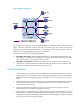
Default-MDT establishment in a PIM-SM network Figure 61 Default-MDT establishment in a PIM-SM network As shown in Figure 61, PIM-SM is enabled in the network and all the PE devices support VPN instance A. The process of establishing a default-MDT is as follows: 1. The public network interface of PE 1 initiates a join to the public network RP by specifying the multicast group address as the default-group address in the join message, and a (*, 239.1.1.
Default-MDT-based delivery The default-MDT delivers multicast protocol packets and multicast data packets differently. Multicast protocol packet delivery To forward the multicast protocol packets of a VPN over the public network, the local PE device encapsulates them into public network multicast data packets. These packets are transmitted along the default-MDT, and then decapsulated on the remote PE device to go into the normal protocol procedure.
Figure 62 Transmission of multicast protocol packets BGP: 11.1.3.1/24 PE 3 Source Receiver RP CE 1 Site 1 P PE 1 PE 2 MD BGP: 11.1.1.1/24 CE 2 BGP: 11.1.2.1/24 Site 2 Public instance BGP peers S: 192.1.1.1/24 G: 225.1.1.1 VPN instance join (*, 225.1.1.1) Default-group: 239.1.1.1 Public instance join (11.1.2.1, 239.1.1.1) The multicast protocol packet is delivered as follows: 1. Receiver sends an IGMP report to CE 2 to join the multicast group G. CE 2 creates a local state entry (*, 225.
VPN multicast data packets are forwarded across the public network differently in the following circumstances: 1. If PIM-DM or PIM-SSM is running in the VPN, the multicast source forwards multicast data packets to the receivers along the VPN SPT across the public network. 2.
5. PE 1 encapsulates the VPN multicast data packet into a public network multicast packet (11.1.1.1, 239.1.1.1) by using the GRE method. The source IP address of the packet is the MD source interface 11.1.1.1 and the destination address is the default-group address 239.1.1.1. PE 1 then forwards it to the public network. 6. The default-MDT forwards the multicast data packet (11.1.1.1, 239.1.1.1) to the public network instance on all the PE devices.
Figure 65 Multi-hop EBGP interconnectivity By using this method, only one MD needs to be established for all the ASs, and public network multicast traffic between different ASs is transmitted within this MD. Multicast VPN configuration task list Task at a glance (Required.) Enabling IP multicast routing in a VPN instance (Required.) Creating the MD for a VPN instance (Required.) Specifying the default-group address (Required.
• Determine the default-group addresses. • Determine the source address for establishing BGP peers. Enabling IP multicast routing in a VPN instance Before you configure any MD-VPN functionality for a VPN, you must create a VPN instance and enable IP multicast routing in this VPN instance. Perform the following configuration on the PE. To enable IP multicast routing in a VPN instance: Step 1. 2. Enter system view. Create a VPN instance and enter VPN instance view.
PE devices. The system prompts error if you specify the same default-group address for different VPN instances. Perform the following configuration on the PE. To specify the default-group: Step Command Remarks 1. Enter system view. system-view N/A 2. Enter MD view. multicast-domain vpn-instance vpn-instance-name N/A 3. Specify a default-group address. default-group group-address By default, no default-group address is specified.
Intra-AS MD VPN configuration example Network requirements Item Network requirements • In VPN instance a, S 1 is a multicast source, and R 1, R 2 and R 3 are receivers. Multicast sources and receivers • In VPN instance b, S 2 is a multicast source, and R 4 is a receiver. • For VPN instance a, the default-group address is 239.1.1.1. • For VPN instance b, the default-group address is 239.2.2.2. • PE 1: Ethernet 1/2 and Ethernet 1/3 belong to VPN instance a.
Figure 66 Network diagram VPN a Loop1 S2 VPN b Eth 1/1 Eth 1/2 Eth CE b1 1/3 Eth 1/2 S1 Eth 1/3 VPN a Eth 1/3 Loop1 1/1 /1 Eth Eth1 Eth1/1 R3 Loop1 Eth Eth1 /2 1/1 Eth 1/2 CE a2 1/2 Eth Loop1 PE 2 R1 Eth 1/1 R2 1/2 h1/2 Eth Et Eth1/1 Eth1/3 Et Eth 1/3 h1/2 PE 3 P CE a3 R4 Loop2 Eth 1/1 1/2 h1/3 Eth Et PE 1 CE b2 Public Loop1 CE a1 Eth1/1 VPN b VPN a Device Interface IP address Device Interface IP address S1 — 10.110.7.2/24 PE 3 Eth1/1 192.168.8.
[PE1-mrib] quit # Configure an MPLS LSR ID and enable the LDP capability. [PE1] mpls lsr-id 1.1.1.1 [PE1] mpls ldp [PE1-ldp] quit # Create VPN instance a and configure an RD and route target attributes for it. [PE1] ip vpn-instance a [PE1-vpn-instance-a] route-distinguisher 100:1 [PE1-vpn-instance-a] vpn-target 100:1 export-extcommunity [PE1-vpn-instance-a] vpn-target 100:1 import-extcommunity [PE1-vpn-instance-a] quit # Enable IP multicast routing in VPN instance a.
[PE1-bgp] peer 1.1.1.3 group vpn-g [PE1–bgp] ip vpn-instance a [PE1-bgp-a] address-family ipv4 [PE1-bgp-ipv4-a] import-route rip 2 [PE1-bgp-ipv4-a] import-route direct [PE1-bgp-ipv4-a] quit [PE1-bgp-a] quit [PE1–bgp] address-family vpnv4 [PE1–bgp-vpnv4] peer vpn-g enable [PE1–bgp-vpnv4] quit [PE1–bgp] quit # Create MD for VPN instance a and specify the default-group address and the MD source interface address for it. [PE1] multicast-domain vpn-instance a [PE1-md-a] default-group 239.1.1.
[PE2-mrib-a] quit # Create VPN instance a and configure an RD and route target attributes for it. [PE2] ip vpn-instance a [PE2-vpn-instance-a] route-distinguisher 100:1 [PE2-vpn-instance-a] vpn-target 100:1 export-extcommunity [PE2-vpn-instance-a] vpn-target 100:1 import-extcommunity [PE2-vpn-instance-a] quit # Enable IP multicast routing in VPN instance a.
[PE2-bgp-ipv4-a] quit [PE2-bgp-a] quit [PE2–bgp] ip vpn-instance b [PE2-bgp-b] address-family ipv4 [PE2-bgp-ipv4-b] import-route rip 3 [PE2-bgp-ipv4-b] import-route direct [PE2-bgp-ipv4-b] quit [PE2-bgp-b] quit [PE2–bgp] address-family vpnv4 [PE2–bgp-vpnv4] peer vpn-g enable [PE2–bgp-vpnv4] quit [PE2–bgp] quit # Create the MD for VPN instance a and specify the default-group address and the MD source interface address for it. [PE2] multicast-domain vpn-instance a [PE2-md-a] default-group 239.1.1.
[PE3] mpls lsr-id 1.1.1.3 [PE3] mpls ldp [PE3-ldp] quit # Create VPN instance a and configure an RD and route target attributes for it. [PE3] ip vpn-instance a [PE3-vpn-instance-a] route-distinguisher 100:1 [PE3-vpn-instance-a] vpn-target 100:1 export-extcommunity [PE3-vpn-instance-a] vpn-target 100:1 import-extcommunity [PE3-vpn-instance-a] quit # Enable IP multicast routing in VPN instance a.
[PE3-LoopBack1] quit # Bind Loopback 2 with VPN instance b, assign an IP address to Loopback 2, and enable PIM-SM on the interface. [PE3] interface loopback 2 [PE3-LoopBack2] ip binding vpn-instance b [PE3-LoopBack2] ip address 33.33.33.33 32 [PE3-LoopBack2] pim sm [PE3-LoopBack2] quit # Configure Loopback 2 as a C-BSR and C-RP for VPN instance b. [PE3] pim vpn-instance b [PE3-pim-b] c-bsr 33.33.33.33 [PE3-pim-b] c-rp 33.33.33.33 [PE3-pim-b] quit # Configure BGP.
# Configure OSPF. [PE3] ospf 1 [PE3-ospf-1] area 0.0.0.0 [PE3-ospf-1-area-0.0.0.0] network 1.1.1.3 0.0.0.0 [PE3-ospf-1-area-0.0.0.0] network 192.168.0.0 0.0.255.255 [PE3-ospf-1-area-0.0.0.0] quit [PE3-ospf-1] quit # Configure RIP. [PE3] rip 2 vpn-instance a [PE3-rip-2] network 10.0.0.0 [PE3-rip-2] import-route bgp [PE3-rip-2] quit [PE3] rip 3 vpn-instance b [PE3-rip-3] network 10.0.0.0 [PE3-rip-3] network 33.0.0.0 [PE3-rip-3] import-route bgp [PE3-rip-3] return 4.
[P-Ethernet1/3] mpls enable [P-Ethernet1/3] mpls ldp enable [P-Ethernet1/3] quit # Assign an IP address to Loopback 1 and enable PIM-SM on the interface. [P] interface loopback 1 [P-LoopBack1] ip address 2.2.2.2 32 [P-LoopBack1] pim sm [P-LoopBack1] quit # Configure Loopback 1 as a C-BSR and C-RP on the public network. [P] pim [P-pim] c-bsr 2.2.2.2 [P-pim] c-rp 2.2.2.2 [P-pim] quit # Configure OSPF. [P] ospf 1 [P-ospf-1] area 0.0.0.0 [P-ospf-1-area-0.0.0.0] network 2.2.2.2 0.0.0.0 [P-ospf-1-area-0.0.0.
# Assign an IP address to Ethernet 1/2 and enable PIM-SM on it. [CEb1] interface ethernet 1/2 [CEb1-Ethernet1/2] ip address 10.110.3.2 24 [CEb1-Ethernet1/2] pim sm [CEb1-Ethernet1/2] quit # Configure RIP. [CEb1] rip 3 [CEb1-rip-3] network 10.0.0.0 7. Configure CE a2: # Enable IP multicast routing. system-view [CEa2] multicast routing [CEa2-mrib] quit # Assign an IP address to Ethernet 1/1 and enable IGMP and PIM-SM on it. [CEa2] interface ethernet 1/1 [CEa2-Ethernet1/1] ip address 10.110.9.
[CEa3] multicast routing [CEa3-mrib] quit # Assign an IP address to Ethernet 1/1, and enable IGMP and PIM-SM on it. [CEa3] interface ethernet 1/1 [CEa3-Ethernet1/1] ip address 10.110.10.1 24 [CEa3-Ethernet1/1] igmp enable [CEa3-Ethernet1/1] pim sm [CEa3-Ethernet1/1] quit # Assign an IP address to Ethernet 1/2 and enable PIM-SM on it. [CEa3] interface ethernet 1/2 [CEa3-Ethernet1/2] ip address 10.110.5.
239.1.1.1 1.1.1.1 MTunnel0 a # Display information about the default-groups in VPN instances on PE 2. [PE2] display multicast-domain default-group Group address Source address Interface VPN instance 239.1.1.1 1.1.1.2 MTunnel0 a 239.1.1.1 1.1.1.2 MTunnel1 b # Display information about the default-groups in VPN instances on PE 3. [PE3] display multicast-domain default-group Group address Source address Interface VPN instance 239.1.1.1 1.1.1.3 MTunnel0 a 239.2.2.2 1.1.1.
Item Network requirements IGMP • Run IGMPv2 on Ethernet 1/1 of CE a2. • Run IGMPv2 on Ethernet 1/1 of CE b2. PIM • • • • Enable PIM-SM on all public network interfaces of PE 2 and PE 3. Enable PIM-SM on all public and private network interfaces of PE 1 and PE 4. Enable PIM-SM on all interfaces of CE a1, CE a2, CE b1, and CE b2. Configure Loopback 2 of PE 2 and PE 3 as a C-BSR and a C-RP for their own AS to provide services for all multicast groups.
Figure 67 Network diagram Lo op 1 Lo op 2 1 op Lo Lo op 2 Device Interface IP address Device Interface IP address S1 — 10.11.5.2/24 R1 — 10.11.8.2/24 S2 — 10.11.6.2/24 R2 — 10.11.7.2/24 PE 1 Eth1/1 10.10.1.1/24 PE 3 Eth1/1 10.10.2.1/24 Eth1/2 10.11.1.1/24 Eth1/2 192.168.1.2/24 Eth1/3 10.11.2.1/24 Loop1 1.1.1.3/32 Loop2 22.22.22.22/32 Eth1/1 10.10.2.2/24 10.11.3.1/24 PE 2 CE a1 CE a2 Loop1 1.1.1.1/32 Eth1/1 10.10.1.2/24 Eth1/2 192.168.1.1/24 Eth1/2 Loop1 1.
[PE1] mpls ldp [PE1-ldp] quit # Create VPN instance a and configure an RD and route target attributes for it. [PE1] ip vpn-instance a [PE1-vpn-instance-a] route-distinguisher 100:1 [PE1-vpn-instance-a] vpn-target 100:1 export-extcommunity [PE1-vpn-instance-a] vpn-target 100:1 import-extcommunity [PE1-vpn-instance-a] quit # Enable IP multicast routing in VPN instance a. [PE1] multicast routing vpn-instance a [PE1-mrib-a] quit # Create VPN instance b and configure an RD and route target attributes for it.
# Configure BGP. [PE1] bgp 100 [PE1-bgp] group pe1-pe2 internal [PE1-bgp] peer pe1-pe2 label-route-capability [PE1-bgp] peer pe1-pe2 connect-interface loopback 1 [PE1-bgp] peer 1.1.1.2 group pe1-pe2 [PE1-bgp] group pe1-pe4 external [PE1-bgp] peer pe1-pe4 as-number 200 [PE1-bgp] peer pe1-pe4 ebgp-max-hop 255 [PE1-bgp] peer 1.1.1.
[PE1-ospf-2] area 0.0.0.0 [PE1-ospf-2-area-0.0.0.0] network 10.11.0.0 0.0.255.255 [PE1-ospf-2-area-0.0.0.0] quit [PE1-ospf-2] quit [PE1] ospf 3 vpn-instance b [PE1-ospf-3] import-route bgp [PE1-ospf-3] area 0.0.0.0 [PE1-ospf-3-area-0.0.0.0] network 10.11.0.0 0.0.255.255 [PE1-ospf-3-area-0.0.0.0] quit [PE1-ospf-3] quit 2. Configure PE 2: # Configure a Router ID and enable IP multicast routing on the public network. system-view [PE2] router id 1.1.1.
[PE2-pim] c-bsr 11.11.11.11 [PE2-pim] c-rp 11.11.11.11 [PE2-pim] quit # Configure BGP. [PE2] bgp 100 [PE2-bgp] address-family ipv4 [PE2-bgp-ipv4] import-route ospf 1 [PE2-bgp-ipv4] quit [PE2-bgp] group pe2-pe1 internal [PE2-bgp] peer pe2-pe1 route-policy map2 export [PE2-bgp] peer pe2-pe1 label-route-capability [PE2-bgp] peer pe2-pe1 connect-interface loopback 1 [PE2-bgp] peer 1.1.1.
# Assign an IP address to the public network interface Ethernet 1/1, and enable PIM-SM, MPLS capability, and LDP capability on it. [PE3] interface ethernet 1/1 [PE3-Ethernet1/1] ip address 10.10.2.1 24 [PE3-Ethernet1/1] pim sm [PE3-Ethernet1/1] mpls enable [PE3-Ethernet1/1] mpls ldp enable [PE3-Ethernet1/1] quit # Assign an IP address to the public network interface Ethernet 1/2, and enable PIM-SM and MPLS on it. [PE3] interface ethernet 1/2 [PE3-Ethernet1/2] ip address 192.168.1.
# Configure OSPF. [PE3] ospf 1 [PE3-ospf-1] area 0.0.0.0 [PE3-ospf-1-area-0.0.0.0] network 1.1.1.3 0.0.0.0 [PE3-ospf-1-area-0.0.0.0] network 22.22.22.22 0.0.0.0 [PE3-ospf-1-area-0.0.0.0] network 10.10.0.0 0.0.255.255 [PE3-ospf-1-area-0.0.0.0] quit [PE3-ospf-1] quit # Configure a routing policy.
[PE4] interface ethernet 1/1 [PE4-Ethernet1/1] ip address 10.10.2.2 24 [PE4-Ethernet1/1] pim sm [PE4-Ethernet1/1] mpls enable [PE4-Ethernet1/1] mpls ldp enable [PE4-Ethernet1/1] quit # Bind Ethernet 1/2 with VPN instance a, assign an IP address to Ethernet 1/2, and enable PIM-SM on the interface. [PE4] interface ethernet 1/2 [PE4-Ethernet1/2] ip binding vpn-instance a [PE4-Ethernet1/2] ip address 10.11.3.
[PE4–bgp] address-family vpnv4 [PE4–bgp-vpnv4] peer 1.1.1.1 enable [PE4–bgp-vpnv4] quit [PE4–bgp] quit # Create the MD for VPN instance a and specify the default-group address and the MD source interface address for it. [PE4] multicast-domain vpn-instance a [PE4-md-a] default-group 239.1.1.1 [PE4-md-a] source loopback 1 [PE4-md-a] quit # Create the MD for VPN instance b and specify the default-group address and the MD source interface address for it.
[CEa1-Ethernet1/2] ip address 10.11.1.2 24 [CEa1-Ethernet1/2] pim sm [CEa1-Ethernet1/2] quit # Assign an IP address to Loopback 1 and enable PIM-SM on this interface. [CEa1] interface loopback 1 [CEa1-LoopBack1] ip address 2.2.2.2 32 [CEa1-LoopBack1] pim sm [CEa1-LoopBack1] quit # Configure Loopback 1 as a C-BSR and a C-RP for VPN instance a. [CEa1] pim [CEa1-pim] c-bsr 2.2.2.2 [CEa1-pim] c-rp 2.2.2.2 1 [CEa1-pim] quit # Configure OSPF. [CEa1] ospf 1 [CEa1-ospf-1] area 0.0.0.0 [CEa1-ospf-1-area-0.0.0.
# Assign an IP address to Ethernet 1/1 and enable IGMP and PIM-SM on this interface. [CEa2] interface ethernet 1/1 [CEa2-Ethernet1/1] ip address 10.11.7.1 24 [CEa2-Ethernet1/1] igmp enable [CEa2-Ethernet1/1] pim sm [CEa2-Ethernet1/1] quit # Assign an IP address to Ethernet 1/2 and enable PIM-SM on this interface. [CEa2] interface ethernet 1/2 [CEa2-Ethernet1/2] ip address 10.11.3.2 24 [CEa2-Ethernet1/2] pim sm [CEa2-Ethernet1/2] quit # Configure OSPF. [CEa2] ospf 1 [CEa2-ospf-1] area 0.0.0.
[CEb2-ospf-1-area-0.0.0.0] network 3.3.3.3 0.0.0.0 [CEb2-ospf-1-area-0.0.0.0] network 10.11.0.0 0.0.255.255 [CEb2-ospf-1-area-0.0.0.0] quit [CEb2-ospf-1] quit Verifying the configuration Use the display multicast-domain default-group command to display the default-group information. # Display information about the default-groups in VPN instances on PE 1. [PE1] display multicast-domain default-group Group address Source address Interface VPN instance 239.1.1.1 1.1.1.1 MTunnel0 a 239.4.4.4 1.1.1.
Solution 1. Use the display interface command to examine the MTI interface state and address encapsulation on the MTI. 2. Use the display multicast-domain default-group command to verify that the same default-group address has been configured for the same VPN instance on different PE devices. 3.
Support and other resources Contacting HP For worldwide technical support information, see the HP support website: http://www.hp.
Conventions This section describes the conventions used in this documentation set. Command conventions Convention Description Boldface Bold text represents commands and keywords that you enter literally as shown. Italic Italic text represents arguments that you replace with actual values. [] Square brackets enclose syntax choices (keywords or arguments) that are optional. { x | y | ... } Braces enclose a set of required syntax choices separated by vertical bars, from which you select one.
Network topology icons Represents a generic network device, such as a router, switch, or firewall. Represents a routing-capable device, such as a router or Layer 3 switch. Represents a generic switch, such as a Layer 2 or Layer 3 switch, or a router that supports Layer 2 forwarding and other Layer 2 features. Represents an access controller, a unified wired-WLAN module, or the switching engine on a unified wired-WLAN switch. Represents an access point.
Index ACDEFHIMOPRST Enabling IP multicast routing,36 A Enabling IPv6 multicast routing,104 Adjusting IGMP performance,53 Adjusting MLD performance,116 F C Feature and hardware compatibility,14 Configuration examples,40 H Configuration task list,35 How MD-VPN works,171 Configuration task list,104 I Configuring basic IGMP functions,51 IGMP configuration example,55 Configuring basic IGMP snooping functions,18 IGMP configuration task list,51 Configuring basic MLD functions,114 IGMP snooping co
S Troubleshooting IPv6 PIM,164 Static port configuration example,27 Troubleshooting MD-VPN,206 Troubleshooting MLD,120 T Troubleshooting multicast routing and forwarding,46 Troubleshooting IGMP,57 Troubleshooting PIM,99 Troubleshooting IGMP snooping,30 212