
HP MSR2000/3000/4000 Router Series IP Multicast Configuration Guide


118
MLD configuration example
Network requirements
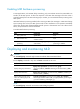
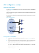
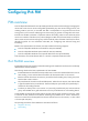
As shown in Figure 42, VOD streams are sent to receiver hosts in multicast. Receiver hosts of different
organizations form stub networks N1 and N2. Host A and Host C are multicast receiver hosts in N1 and
N2, respectively.
MLDv1 runs between Router A and N1, and between the other two routers (Router B and Router C) and
N2. Router A acts as the MLD querier in N1. Router B acts as the MLD querier in N2 because it has a
lower IPv6 address.
The hosts in N1 can only join the IPv6 multicast group FF1E::101. The hosts in N2 can join any IPv6
multicast groups.
Figure 42 Network diagram
Configuration procedure
1. Assign an IPv6 address and prefix length to each interface as shown in Figure 42. (Details not
shown.)
2. Configure OSPFv3 between the routers on the IPv6 PIM network to make sure the network-layer is
interoperable on the IPv6 PIM network and routing information among the routers can be
dynamically updated. (Details not shown.)
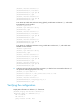
3. Enable the IPv6 multicast routing, MLD, and IPv6 PIM-DM:
# On Router A, enable IPv6 multicast routing globally, enable MLD on Ethernet 1/1, and enable
IPv6 PIM-DM on each interface.
<RouterA> system-view
[RouterA] ipv6 multicast routing
[RouterA-mrib6] quit
Router A
Router B
Router C
Querier
IPv6 PIM network
N1
N2
Receiver
Receiver
Host A
Host B
Host C
Host D
Eth1/1
3000::12/64
Eth1/1
3001::10/64
Eth1/1
3001::12/64
E
t
h
1
/
2
E
t
h
1
/
2
E
t
h
1
/
2