
HP MSR2000/3000/4000 Router Series IP Multicast Configuration Guide

153
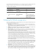
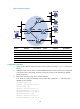
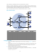
Host A and Host C are multicast receivers in the stub networks N1 and N2.
Ethernet1/3 on Router D and Ethernet1/3 on Router E act as C-BSRs and C-RPs. The C-BSR on Router E
has a higher priority. The C-RPs are designated to the IPv6 multicast group range FF0E::101/64. Modify
the hash mask length to map the IPv6 multicast group range to the two C-RPs.
MLDv1 runs between Router A and N1, and between Router B, Router C, and N2.
Figure 53 Network diagram
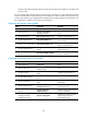
Device Interface IPv6 address
Device
Interface
IPv6 address
Router A Eth1/1 1001::1/64
Router D
Eth1/1
4001::1/64
Eth1/2 1002::1/64 Eth1/2 1002::2/64
Eth1/3 1003::1/64
Eth1/3
4002::1/64
Router B Eth1/1 2001::1/64
Router E
Eth1/1
3001::2/64
Eth1/2 2002::1/64 Eth1/2 2002::2/64
Router C Eth1/1 2001::2
/
64
Eth1/3
1003::2/64
Eth1/2 3001::1/64
Eth1/4
4002::2
/
64
Configuration procedure
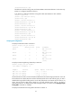
1. Assign an IPv6 address and prefix length to each interface according to Figure 53. (Details not
shown.)
2. Enable OSPFv3 on all routers on the IPv6 PIM-SM network to make sure the network-layer on the
IPv6 PIM-SM network is interoperable and the routing information among the routers can be
dynamically updated. (Details not shown.)
3. Enable IPv6 multicast routing, and enable MLD and IPv6 PIM-SM:
# On Router A, enable IPv6 multicast routing globally, enable MLD on Ethernet 1/1, and enable
IPv6 PIM-SM on each interface.
<RouterA> system-view
Ethernet
EthernetEthernet
N1N2
Eth1/2
Eth1/2