
HP MSR2000/3000/4000 Router Series IP Multicast Configuration Guide


177
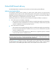
5. PE 1 encapsulates the VPN multicast data packet into a public network multicast packet (11.1.1.1,
239.1.1.1) by using the GRE method. The source IP address of the packet is the MD source
interface 11.1.1.1 and the destination address is the default-group address 239.1.1.1. PE 1 then
forwards it to the public network.
6. The default-MDT forwards the multicast data packet (11.1.1.1, 239.1.1.1) to the public network
instance on all the PE devices. After receiving this packet, every PE device decapsulates it to get the
original VPN multicast data packet, and passes it to the corresponding VPN instance. If a PE
device has a downstream interface for an SPT, it forwards the VPN multicast packet down the SPT.
Otherwise, it discards the packet.
7. The VPN instance on PE 2 looks up the MVRF and finally delivers the VPN multicast data to
Receiver.
By now, the process of transmitting a VPN multicast data packet across the public network is
completed.
Inter-AS MD VPN
If the nodes of a VPN network are allocated in multiple ASs, these VPN nodes must be interconnected.
To implement inter-AS VPN, VRF-to-VRF PE interconnectivity and multi-hop EBGP interconnectivity are
available.
VRF-to-VRF PE interconnectivity
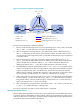
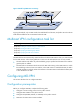
As shown in Figure 64, a VPN involves AS 1 and AS 2. PE 3 and PE 4 are ASBRs for AS 1 and AS 2,
respectively. PE 3 and PE 4 are interconnected through their respective VPN instance and treat each
other as a CE device.
Figure 64 VPN instance-VPN instance interconnectivity
By using this method, a separate MD must be established within each AS, and VPN multicast data traffic
between different ASs is transmitted between the two MDs.
Because only VPN multicast data traffic is forwarded between ASBRs, different PIM modes can run within
different ASs. However, the same PIM mode must run on all interfaces that belong to the same VPN
(including interfaces with VPN bindings on ASBRs).
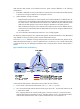
Multi-hop EBGP interconnectivity
As shown in Figure 65, a VPN network involves AS 1 and AS 2. PE 3 and PE 4 are the ASBRs for AS 1
and AS 2, respectively. PE 3 and PE 4 are interconnected through their respective public network
instance and treat each other as a P device.