
HP MSR2000/3000/4000 Router Series IP Multicast Configuration Guide

195
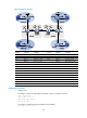
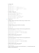
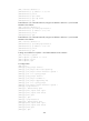
Figure 67 Network diagram
Device Interface IP address Device Interface IP address
S 1 — 10.11.5.2
/
24
R 1
—
10.11.8.2
/
24
S 2 — 10.11.6.2
/
24
R 2
—
10.11.7.2
/
24
PE 1 Eth1/1 10.10.1.1/24 PE 3 Eth1/1 10.10.2.1/24
Eth1/2 10.11.1.1/24
Eth1/2
192.168.1.2
/
24
Eth1/3 10.11.2.1
/
24
Loop1
1.1.1.3
/
32
Loop1 1.1.1.1/32 Loop2 22.22.22.22/32
PE 2 Eth1/1 10.10.1.2/24
PE 4
Eth1/1
10.10.2.2/24
Eth1/2 192.168.1.1/24
Eth1/2
10.11.3.1/24
Loop1 1.1.1.2/32 Eth1/3 10.11.4.1/32
Loop2 11.11.11.11/32
Loop2
1.1.1.4/32
CE a1 Eth1/1 10.11.5.1/24
CE b1
Eth1/1
10.11.6.1
/
24
Eth1/2 10.11.1.2/24 Eth1/2 10.11.2.2/24
Loop0 2.2.2.2/32
CE b2
Eth1/1
10.11.8.1
/
24
CE a2 Eth1/1 10.11.7.1
/
24
Eth1/2
10.11.4.2
/
24
Eth1/2 10.11.3.2/24 Loop0 3.3.3.3/32
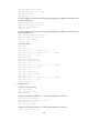
Configuration procedure
1. Configure PE 1:
# Configure a Router ID and enable IP multicast routing on the public network.
<PE1> system-view
[PE1] router id 1.1.1.1
[PE1] multicast routing
[PE1-mrib] quit
# Configure an MPLS LSR ID and enable the LDP capability.
[PE1] mpls lsr-id 1.1.1.1
L
o
o
p
2
L
o
o
p
2
L
oop1
Lo
op
1