
HP MSR2000/3000/4000 Router Series IP Multicast Configuration Guide

89
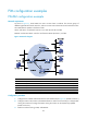
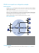
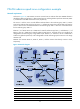
PIM-SM non-scoped zone configuration example
Network requirements
As shown in Figure 34, VOD streams are sent to receiver hosts in multicast. The receivers of different
subnets form stub networks, and at least one receiver host exist in each stub network. The entire PIM-SM
domain contains only one BSR.
Host A and Host C are multicast receivers in the stub networks N1 and N2.
Ethernet 1/3 on Router D and Ethernet 1/3 on Router E act as C-BSRs and C-RPs. The C-BSR on Router
E has a higher priority. The C-RPs are designated to the multicast group range 225.1.1.0/24. Modify the
hash mask length to map the multicast group range to the two C-RPs.
IGMPv2 runs between Router A and N1, and between Router B, Router C, and N2.
Figure 34 Network diagram
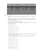
Device Interface IP address Device Interface IP address
Router A Eth1/1 10.110.1.1/24
Router D
Eth1/1
10.110.5.1/24
Eth1/2 192.168.1.1/24
Eth1/2
192.168.1.2/24
Eth1/3 192.168.9.1/24 Eth1/3 192.168.4.2/24
Router B Eth1/1 10.110.2.1/24
Router E
Eth1/1
192.168.3.2/24
Eth1/2 192.168.2.1/24
Eth1/2
192.168.2.2/24
Router C Eth1/1 10.110.2.2/24 Eth1/3 192.168.9.2/24
Eth1/2 192.168.3.1/24
Eth1/4
192.168.4.1/24
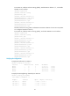
Configuration procedure
1. Assign an IP address and subnet mask to each interface according to Figure 34. (Details not
shown.)
Source
10.110.5.100/24
PIM-SM
Router A
Router B
Router C
Router D
Receiver
Host A
Host B
Host C
Host D
Receiver
Router E
Eth1/1
Eth1/1
Eth1/1
Eth1/1
Eth1/3
Eth1/3
Eth1/
2
Et
h1/2
Eth1/2
Eth1/2
Eth1/2
Eth1/1
Eth1/4
Eth1/3