
HP MSR2000/3000/4000 Router Series Layer 2 - LAN Switching Configuration Guide

43
Task Command
Display the statistics of TC/TCN BPDUs sent and received
by all ports in the specified MSTI or all MSTIs (MSR4000).
display stp [ instance instance-list ] tc [ slot
slot-number ]
Display the spanning tree status and statistics
(MSR2000/MSR3000).
display stp [ instance instance-list ] [ interface
interface-list ] [ brief ]
Display the spanning tree status and statistics (MSR4000).
display stp [ instance instance-list ] [ interface
interface-list | slot slot-number ] [ brief ]
Display the MST region configuration information that has
taken effect.
display stp region-configuration
Display the root bridge information of all MSTIs. display stp root
Clear the spanning tree statistics. reset stp [ interface interface-list ]
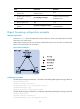
Spanning tree configuration example
MSR4000 does not support the configuration example in this section.
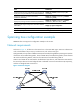
Network requirements
As shown in Figure 12, all devices on the network are in the same MST region. Device A and Device B
work at the distribution layer. Device C and Device D work at the access layer.
Configure MSTP so that packets of different VLANs are forwarded along different spanning trees: Packets
of VLAN 10 are forwarded along MSTI 1, those of VLAN 30 are forwarded along MSTI 3, those of VLAN
40 are forwarded along MSTI 4, and those of VLAN 20 are forwarded along MSTI 0.
VLAN 10 and VLAN 30 are terminated on the distribution layer devices, and VLAN 40 is terminated on
the access layer devices. The root bridges of MSTI 1 and MSTI 3 are Device A and Device B, respectively,
and the root bridge of MSTI 4 is Device C.
Figure 12 Network diagram
E
t
h
2
/
1
E
t
h
2
/
1
E
t
h
2
/
1
E
t
h
2
/
1