HP MSR2000/3000/4000 Router Series Layer 2 - WAN Access Configuration Guide (V7) Part number: 5998-3989 Software version: CMW710-R0007P02 Document version: 6PW100-20130927
Legal and notice information © Copyright 2013 Hewlett-Packard Development Company, L.P. No part of this documentation may be reproduced or transmitted in any form or by any means without prior written consent of Hewlett-Packard Development Company, L.P. The information contained herein is subject to change without notice.
Contents Configuring PPP and MP ············································································································································· 1 PPP overview······································································································································································ 1 PPP link establishment process ····························································································································
Specifying LNS IP addresses ································································································································ 42 Configuring transferring AVP data in hidden mode ·························································································· 42 Configuring AAA authentication on an LAC ······································································································ 42 Configuring an LAC to automatically establish an L2TP tunnel ·
Managing a modem ·················································································································································· 75 Modem management configuration task list ··············································································································· 75 Configuring modem access services on a user line ··································································································· 75 Setting the answer timeout timer·····
Configuring ISDN caller identification callback with C-DDR ·········································································· 104 Configuring ISDN caller identification callback with B-DDR ·········································································· 106 Configuring auto-dial ··················································································································································· 107 Configuring circular dial string backup ······················
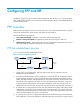
Configuring PPP and MP This feature is supported only on routers installed with SAE, AS, ASE, BS, E1, E1-F, T1, T1-F, POS, CPOS, CE3, or AM interface modules. For more information about interface modules, see HP MSR Router Series Interface Module Guide. PPP overview Point-to-Point Protocol (PPP) is a point-to-point link layer protocol. It provides user authentication, supports synchronous/asynchronous communication, and allows for easy extension.
becomes ready to carry negotiated network-layer protocol packets. If the NCP negotiation fails, NCP reports a Down event and enters the Link Termination phase. If the interface is configured with an IP address, the IPCP negotiation is performed. IPCP configuration options include IP addresses and DNS server IP addresses. After the IPCP negotiation succeeds, the link can carry IP packets. 5.
Tasks at a glance (Optional.) Configuring PPP authentication (Optional.) Configuring the polling interval (Optional.) Configuring PPP negotiation Enabling PPP encapsulation on an interface Step Command Remarks 1. Enter system view. system-view N/A 2. Enter interface view. interface interface-type interface-number N/A 3. Enable PPP encapsulation on the interface. link-protocol ppp By default, all interfaces except Ethernet interfaces and VLAN interfaces use PPP as the link layer protocol.
To configure the peer: Step Command Remarks 1. Enter system view. system-view N/A 2. Enter interface view. interface interface-type interface-number N/A 3. Configure the PAP username and password sent from the peer to the authenticator when the peer is authenticated by the authenticator by using PAP.
Step Enter interface view. 2. Command Remarks interface interface-type interface-number N/A The default setting is null. Configure a username for the CHAP peer. 3. ppp chap user username For local AAA authentication, the username and password of the authenticator must be configured on the peer. For remote AAA authentication, the username and password of the authenticator must be configured on the remote AAA server. Configure local or remote AAA authentication. 4.
Step Command Remarks The default setting is null. Configure a username for the CHAP peer. 3. ppp chap user username The username you configure on the peer must be the same as the local username you configure for the peer on the authenticator. The default setting is null. Set the CHAP authentication password. 4. ppp chap password { cipher | simple } password The password you set on the peer must be the same as the password you set for the peer on the authenticator.
Step Command Remarks 1. Enter system view. system-view N/A 2. Enter interface view. interface interface-type interface-number N/A 3. Configure the negotiation timeout time. ppp timer negotiate seconds The default setting is 3 seconds. Configuring IP address negotiation The device can perform IP address negotiation during IPCP negotiation. Through IP address negotiation, one end can assign an IP address to the other.
For clients requiring no authentication, you can use either method 1 or method 2, but not both. For clients requiring authentication, you can use one or more of the three methods, but cannot use method 1 and method 2 at the same time. When multiple methods are configured, method 3 takes precedence over method 1 or method 2. To configure the device as the server (Method 1): Step Command Remarks 1. Enter system view. system-view N/A 2. Enter interface view.
Step Command Remarks 6. Enter interface view. interface interface-type interface-number N/A 7. Configure an IP address for the interface. ip address ip-address By default, no IP address is configured on an interface. Configuring DNS server IP address negotiation IPCP negotiation can also determine the DNS server IP address. You can configure a device to allocate the DNS server IP address to the peer or receive the DNS server IP address from the peer.
Step Specify the primary and secondary DNS server IP addresses to be allocated to the peer in PPP negotiation.. 3. Command Remarks ppp ipcp dns primary-dns-address [ secondary-dns-address ] By default, a device does not allocate DNS server IP addresses to its peer if the peer does not request them. Configuring MP You can configure MP by using virtual template (VT) or MP-group interfaces. • VT interfaces are used to configure VA interfaces.
Step Command Remarks bandwidth bandwidth-value By default, the expected bandwidth (in kbps) is the interface baud rate divided by 1000. 6. Set the expected bandwidth of the VT interface. 7. (Optional.) Specify a card to forward traffic for the VA interfaces of the VT interface. service slot slot-number (Optional.) Restore the default settings for the VT interface. default 8. By default, no card is specified. Only the MSR4000 routers support this function.
Step Command Remarks 10. Set the MTU size of the interface. mtu size The default setting is 1500 bytes. 11. Set the expected bandwidth of the interface. bandwidth bandwidth-value By default, the expected bandwidth (in kbps) is the interface baud rate divided by 1000. 12. (Optional.) Restore the default settings for the interface. default N/A 13. Bring up the interface. undo shutdown By default, an interface is up. 14. Return to system view. quit N/A 15. Enter interface view.
Configuring LFI Real-time packets such as Telnet and VoIP packets might be blocked or delayed on a low-speed interface that is processing lots of large packets. To reduces delays and jitters on low-speed links, LFI fragments large packets into small fragments. The fragments are reassembled at the destination. Figure 2 illustrates the LFI process.
Task Command Remarks Display address pools. display ip pool [ pool-name ] [ group group-name ] Available in any view. Display information about VT interfaces. Display information about MP-group interfaces.
[RouterA] interface serial 2/0 [RouterA-Serial2/0] link-protocol ppp # Set the authentication mode to PAP. [RouterA-Serial2/0] ppp authentication-mode pap domain system # Assign an IP address to Serial 2/0. [RouterA-Serial2/0] ip address 200.1.1.1 16 [RouterA-Serial2/0] quit # Configure local authentication for the PPP users in the default ISP domain system. [RouterA] domain system [RouterA-isp-system] authentication ppp local 2.
5 packet(s) transmitted, 5 packet(s) received, 0.0% packet loss round-trip min/avg/max/std-dev = 1.738/2.402/3.197/0.576 ms Two-way PAP authentication configuration example Network requirements As shown in Figure 4, configure Router A and Router B to authenticate each other. Figure 4 Network diagram Configuration procedure 1. Configure Router A: # Create a user account for Router B. system-view [RouterA] local-user userb class network # Set a password for the user account.
[RouterB-luser-network-usera] service-type ppp [RouterB-luser-network-usera] quit # Enable PPP encapsulation on Serial 2/0 (optional, as an interface uses PPP encapsulation by default). [RouterB] interface serial 2/0 [RouterB-Serial2/0] link-protocol ppp # Set the authentication mode to PAP. [RouterB-Serial2/0] ppp authentication-mode pap domain system # Configure the PAP username and password sent from Router B to Router A when Router B is authenticated by Router A using PAP.
One-way CHAP authentication configuration example Network requirements As shown in Figure 5, configure Router A to authenticate Router B by using CHAP. Figure 5 Network diagram Configuration procedure (Method 1) The authenticator configured with a username authenticates the peer by using CHAP. 1. Configure Router A: # Create a user account for Router B. system-view [RouterA] local-user userb class network # Set a password for the user account.
# Enable PPP encapsulation on Serial 2/0 (optional, as an interface uses PPP encapsulation by default). [RouterB] interface serial 2/0 [RouterB-Serial2/0] link-protocol ppp # Configure the username for Router B when Router B is authenticated. [RouterB-Serial2/0] ppp chap user userb # Assign an IP address to Serial 2/0 of Router B. [RouterB-Serial2/0] ip address 200.1.1.2 16 (Method 2) The authenticator with no username configured authenticates the peer by using CHAP. 3.
Description: Serial2/0 Interface Bandwidth: 64kbps Maximum Transmit Unit: 1500 Internet Address: 200.1.1.2/16 Primary Link layer protocol: PPP LCP opened, IPCP opened … [RouterB-Serial2/0] ping 200.1.1.1 Ping 200.1.1.1 (200.1.1.1): 56 data bytes, press escape sequence to break 56 bytes from 200.1.1.1: icmp_seq=0 ttl=128 time=3.197 ms 56 bytes from 200.1.1.1: icmp_seq=1 ttl=128 time=2.594 ms 56 bytes from 200.1.1.1: icmp_seq=2 ttl=128 time=2.739 ms 56 bytes from 200.1.1.1: icmp_seq=3 ttl=128 time=1.
# After the configuration is complete, display summary information about Serial 2/0 on Router B. [RouterB-Serial2/0] display interface serial 2/0 brief Brief information on interface(s) under route mode: Link: ADM - administratively down; Stby - standby Protocol: (s) - spoofing Interface Link Protocol Main IP S2/0 UP UP Description 200.1.1.10 The output shows Serial 2/0 obtains IP address 200.1.1.10 through PPP negotiation. # Ping Serial 2/0 of Router A from Router B. [RouterB-Serial2/0] ping 200.1.
system-view [RouterB] interface serial 2/0 [RouterB-Serial2/0] ip address ppp-negotiate 3. Verify the configuration: # After the configuration is complete, display summary information about Serial 2/0 on Router B. [RouterB-Serial2/0] display interface serial 2/0 brief Brief information on interface(s) under route mode: Link: ADM - administratively down; Stby - standby Protocol: (s) - spoofing Interface Link Protocol Main IP S2/0 UP UP Description 200.1.1.
Configuration procedure 1. Configure Router A: # Configure an address pool aaa that contains IP addresses 200.1.1.10 through 200.1.1.20 for the group AAA. system-view [RouterA] ip pool aaa 200.1.1.10 200.1.1.20 group AAA # Create a local user for Router B. [RouterA] local-user userb class network # Set a password for the local user. [RouterA-luser-network-userb] password simple 123 # Set the service type to PPP for the local user.
56 bytes from 200.1.1.1: icmp_seq=2 ttl=128 time=2.739 ms 56 bytes from 200.1.1.1: icmp_seq=3 ttl=128 time=1.738 ms 56 bytes from 200.1.1.1: icmp_seq=4 ttl=128 time=1.744 ms --- Ping statistics for 200.1.1.1 --5 packet(s) transmitted, 5 packet(s) received, 0.0% packet loss round-trip min/avg/max/std-dev = 1.738/2.402/3.197/0.576 ms The output shows that the ping operation is successful. # Display the address pools on Serial 2/0 of Router A.
[RouterA-Serial2/0] ppp mp mp-group 1 [RouterA-Serial2/0] shutdown [RouterA-Serial2/0] undo shutdown [RouterA-Serial2/0] quit 2. Configure Router B: # Create an MP-group interface and configure an IP address for it. [RouterB] interface mp-group 1 [RouterB-Mp-group1] ip address 1.1.1.2 24 [RouterB-Mp-group1] quit # Configure interface Serial 2/1.
Link layer protocol: PPP LCP: opened, MP: opened, IPCP: opened Physical: MP Last clearing of counters: Never Last 300 seconds input rate: 0 bytes/sec, 0 bits/sec, 0 packets/sec Last 300 seconds output rate: 0 bytes/sec, 0 bits/sec, 0 packets/sec Input: 2 packets, 80 bytes, 0 drops Output: 2 packets, 24 bytes, 0 drops # Ping Router B from Router A. [RouterA] ping 1.1.1.2 Ping 1.1.1.2 (1.1.1.2): 56 data bytes, press escape sequence to break 56 bytes from 1.1.1.2: icmp_seq=0 ttl=255 time=4.
Configuring PPPoE Overview Point-to-Point Protocol over Ethernet (PPPoE) extends PPP by transporting PPP frames encapsulated in Ethernet over point-to-point links. PPPoE specifies the methods for establishing PPPoE sessions and encapsulating PPP frames over Ethernet. PPPoE requires a point-to-point relationship between peers instead of a point-to-multipoint relationship as in multi-access environments such as Ethernet.
• As shown in Figure 11, a PPPoE session is established between each host (PPPoE client) and the carrier router (PPPoE server). The service provider assigns an account to each host for billing and control. The host must be installed with PPPoE client software. Figure 11 Network structure 2 PPPoE client Host A PPPoE server Internet PPPoE client Router Host B PPPoE client PPPoE is widely used in ADSL environments.
Configuring a PPPoE client PPPoE client configuration includes dialer interface configuration and PPPoE session configuration. A PPPoE session can operate in one of the following modes: • Permanent mode—A PPPoE session is established immediately when the line is physically up. This type of session remains until the physical link comes down or until the session is disconnected.
Step 6. Associate the interface with the dial access control rule by associating the interface with the corresponding dialer access group. Command Remarks dialer-group group-number By default, a dialer interface is not assigned to any dialer group. The default setting is 120 seconds. 7. 8. Configure the link-idle timeout timer. Configure the DDR application to operate in diagnostic mode.
Resetting a PPPoE session After you reset a PPPoE session in permanent mode, the device establishes a new PPPoE session when the autodial timer expires. After you reset a PPPoE session in on-demand mode, the device establishes a new PPPoE session when there is a demand for data transmission. To reset a PPPoE session: Step Reset a PPPoE session. 1. Command Remarks reset pppoe-client { all | dial-bundle-number number } Available in user view.
[RouterB] dialer-group 1 rule ip permit # Enable bundle DDR on interface Dialer 1. [RouterB] interface dialer 1 [RouterB-Dialer1] dialer bundle enable # Associate interface Dialer 1 with dialer access group 1. [RouterB-Dialer1] dialer-group 1 [RouterB-Dialer1] quit # Configure a PPPoE session that corresponds to dialer bundle 1 (dialer bundle 1 corresponds to interface Dialer 1).
Configuring L2TP Overview The Layer 2 Tunneling Protocol (L2TP) is the most widely used Virtual Private Dialup Network (VPDN) tunneling protocol. L2TP sets up point-to-point tunnels across a public network (for example, the Internet) and transmits encapsulated PPP frames (L2TP packets) over the tunnels. With L2TP, remote users (for example, remote branches and mobile workers) can access the corporate intranets through L2TP tunnels after connecting to a public network by using PPP.
L2TP message types and encapsulation structure L2TP uses the following types of messages: • Control messages—Used to establish, maintain, and delete L2TP tunnels and sessions. Control messages are transmitted over a reliable control channel, which supports flow control and congestion control. • Data messages—Used to encapsulate PPP frames, as shown in Figure 15. Data messages are transmitted over an unreliable data channel and are not retransmitted when packet loss occurs.
Figure 17 NAS-initiated tunneling mode A NAS-initiated tunnel has the following characteristics: • The remote system only needs to support PPP, and does not need to support L2TP. • Authentication and accounting of the remote system can be implemented on the LAC or the LNS. Figure 18 Establishment process for NAS-initiated tunnels As shown in Figure 18, the following workflow is used to establish a NAS-initiated tunnel: 1. A remote system (Host A) initiates a PPP connection to the LAC (Device A). 2.
4. The LAC sends the authentication information (username and password) to its RADIUS server (RADIUS server A) for authentication. 5. RADIUS server A authenticates the user and returns the result. 6. If the user passes the authentication and the user is determined to be an L2TP user according to the username or the ISP domain to which the user belongs, the LAC initiates an L2TP tunneling request to the LNS (Device B). 7.
As shown in Figure 20, the workflow for establishing a client-initiated tunnel is similar to that for establishing a NAS-initiated tunnel. (Details not shown.
Figure 22 Establishment process for LAC-auto-initiated tunnels Remote system Host A LAC Device A LNS Device B RADIUS server (1) Tunnel setup request (2) CHAP authentication (challenge/response) (3) Setup a session (4) LCP negotiation and user authentication (5) Access request (6) Acesss accept (7) Authentication passes, and assign an IP address (8) Access the enterprise network L2TP features • Flexible identity authentication mechanism and high security—L2TP by itself does not provide security for con
Table 1 Tunnel attributes that can be issued by the RADIUS server Attribute number Attribute name Description 64 Tunnel-Type Tunnel type, which can only be L2TP. 65 Tunnel-Medium-Type Transmission medium type for the tunnel, which can only be IPv4. 67 Tunnel-Server-Endpoint IP address of the LNS. 69 Tunnel-Password Key used to authenticate a peer of the tunnel. Group ID for the tunnel.
Tasks at a glance Remarks Configuring an LAC The first task is required for NAS-initiated mode and unnecessary for LAC-auto-initiated mode. • • • • • (Required.) Configuring an LAC to initiate tunneling requests (Required.) Specifying LNS IP addresses (Optional.) Configuring transferring AVP data in hidden mode (Required.) Configuring AAA authentication on an LAC (Required.
Configuring the local tunnel name—The local tunnel name identifies the tunnel at the local end during tunnel negotiation between an LAC and an LNS. • To configure basic L2TP capabilities: Step Command Remarks 1. Enter system view. system-view N/A 2. Enable L2TP. l2tp enable By default, L2TP is disabled. 3. Create an L2TP group, specify its mode, and enter its view. l2tp-group group-number mode { lac | lns } By default, no L2TP group exists.
Specifying LNS IP addresses You can specify up to five LNS IP addresses. The LAC initiates an L2TP tunneling request to its specified LNSs consecutively in their configuration order until it receives an acknowledgement from an LNS, which then becomes the tunnel peer. To specify LNS IP addresses: Step Command Remarks 1. Enter system view. system-view N/A 2. Enter L2TP group view in LAC mode. l2tp-group group-number [ mode lac ] N/A 3. Specify LNS IP addresses.
For more information about configuring AAA authentication, see Security Configuration Guide. To enable AAA authentication on an LAC, you also need to configure the authentication type of PPP users as PAP or CHAP on the user access interfaces. For information about configuring PAP or CHAP, see "Configuring PPP and MP.
Step Command Remarks bandwidth bandwidth-value By default, the expected bandwidth (in kbps) is 0. 10. (Optional.) Restore the default settings for the interface. default N/A 11. (Optional.) Bring up the interface. undo shutdown By default, an interface is up. (Optional.) Configure the expected bandwidth of the interface. 9. Configuring an LNS An LNS responds to the tunneling requests from an LAC, authenticates users, and assigns IP addresses to users.
Step 3. Configure the LNS to accept tunneling requests from a specified LAC and specify the VT interface to use for tunnel setup. Command Remarks • If the L2TP group number is 1: Use either command. allow l2tp virtual-template virtual-template-number [ remote remote-name ] • If the L2TP group number is not 1: allow l2tp virtual-template virtual-template-number remote remote-name By default, an LNS denies tunneling requests from any LACs.
Step Command Remarks 1. Enter system view. system-view N/A 2. Enter L2TP group view in LNS mode. l2tp-group group-number [ mode lns ] N/A 3. Configure mandatory CHAP authentication. mandatory-chap By default, CHAP authentication is not performed on an LNS. This command is effective only on NAS-initiated L2TP tunnels. Configuring LCP renegotiation To establish a NAS-initiated L2TP tunnel, a user first negotiates with the LAC at the start of a PPP session.
LNS side AAA configurations are similar to those on an LAC (see "Configuring AAA authentication on an LAC"). Configuring optional L2TP parameters These optional L2TP parameter configuration tasks apply to both LACs and LNSs. Configuring L2TP tunnel authentication You can enable tunnel authentication to allow the LAC and LNS to authenticate each other. Either the LAC or the LNS can initiate a tunnel authentication request.
Enabling session flow control The L2TP session flow control function adds sequence numbers to transmitted packets, and uses them to reorder packets arriving out of order and to detect lost packets. This function takes effect on both sent and received L2TP data messages. The L2TP sessions support this function if either the LAC or LNS is enabled with this function. To enable session flow control: Step Command Remarks 1. Enter system view. system-view N/A 2. Enter L2TP group view.
Step Command Remarks By default, a tunnel peer belongs to the public network. Configure the VPN to which the tunnel peer belongs. 3. The physical port connecting to the tunnel peer and the tunnel peer should belong to the same VPN. The VPN to which this physical port belongs is configured by using the ip binding vpn-instance command. vpn-instance vpn-instance-name Displaying and maintaining L2TP Execute display commands in any view and reset commands in user view.
system-view [LAC] local-user vpdnuser class network [LAC-luser-network-vpdnuser] password simple Hello [LAC-luser-network-vpdnuser] service-type ppp [LAC-luser-network-vpdnuser] quit # Configure local authentication for PPP users in ISP domain system. [LAC] domain system [LAC-isp-system] authentication ppp local [LAC-isp-system] quit # Configure CHAP authentication on interface Async 1/0. [LAC] interface async 1/0 [LAC-Async1/0] ppp authentication-mode chap [LAC-Async1/0] quit # Enable L2TP.
[LNS-virtual-template1] remote address 192.168.0.2 [LNS-virtual-template1] quit # Create L2TP group 1 in LNS mode, configure the local tunnel name as LNS, and specify Virtual-Template 1 for receiving calls from a specified LAC. [LNS] l2tp-group 1 mode lns [LNS-l2tp1] tunnel name LNS [LNS-l2tp1] allow l2tp virtual-template 1 remote LAC # Enable tunnel authentication, and specify the tunnel authentication key as aabbcc.
[LNS] interface ethernet 1/1 [LNS-Ethernet1/1] ip binding vpn-instance vpn1 [LNS-Ethernet1/1] quit # Configure IP addresses for the interfaces. (Details not shown.) # Configure the route between the LNS and the remote host. (Details not shown.) # Create a local user named vpdnuser, set the password, and enable the PPP service.
Verifying the configuration # On the remote host, initiate the L2TP connection. After the connection is established, the remote host can obtain the IP address 192.168.0.2 and ping the private IP address of the LNS (192.168.0.1). # On the LNS, use the display l2tp session command to check the established L2TP session. [LNS-l2tp1] display l2tp session LocalSID RemoteSID LocalTID State 89 36245 10878 Established # On the LNS, use the display l2tp tunnel command to check the established L2TP tunnel.
[LNS-isp-system] quit # Enable L2TP, and create L2TP group 1 in LNS mode. [LNS] l2tp enable [LNS] l2tp-group 1 mode lns # Configure the local tunnel name as LNS, and specify Virtual-Template 1 for receiving tunneling requests from a specified LAC. [LNS-l2tp1] tunnel name LNS [LNS-l2tp1] allow l2tp virtual-template 1 remote LAC # Enable tunnel authentication, and configure the authentication key as aabbcc.
LocalSID 21409 RemoteSID LocalTID State 3395 4501 Established # On the LNS, use the display l2tp tunnel command to display the established L2TP tunnel. [LNS] display l2tp tunnel LocalTID RemoteTID State Sessions RemoteAddress RemotePort RemoteName 4501 1 1701 524 Established 3.3.3.1 LAC # On the LNS, you should be able to ping 10.2.0.1, a private network address on the LAC side. This indicates that hosts on 10.2.0.0/16 and those on 10.1.0.
Analysis and solution Possible reasons for the data transmission failure are as follows: • No route is available. The LAC must have a route to the private network behind the LNS, and vice versa. Otherwise, data transmission fails. You can use the display ip routing-table command on the LAC and LNS to check whether the expected routes are present. If not, configure a static route, or configure a dynamic routing protocol. • Congestion occurs on the Internet backbone, and the packet loss ratio is high.
Configuring HDLC This feature is supported only on routers installed with SAE, E1, E1-F, T1, T1-F, POS, CPOS, CT3, or CE3 interface modules. For more information about interface modules, see HP MSR Router Series Interface Module Guide. High-level Data Link Control (HDLC) is a bit-oriented link layer protocol. Its most prominent feature is that it can transmit any type of bit stream transparently. • HDLC supports point-to-point link only and does not support point-to-multipoint link.
Step Command Remarks 1. Enter system view. system-view N/A 2. Enter interface view. interface interface-type interface-number N/A 3. Configure the link status polling interval. timer hold seconds Optional. The default setting is 10 seconds. Displaying and maintaining HDLC Execute display commands in any view and reset commands in user view. Task Command Display the HDLC configuration on an interface.
[RouterB-Pos5/0] link-protocol hdlc [RouterB-Pos5/0] ip address 12.1.1.2 24 3. Verify the configurations by pinging Router B from Router A and pinging Router A from Router B. The following example uses the output on Router A: [RouterA] ping 12.1.1.2 Ping 12.1.1.2 (12.1.1.2): 56 data bytes, press escape sequence to break 56 bytes from 12.1.1.2: icmp_seq=0 ttl=254 time=2.137 ms 56 bytes from 12.1.1.2: icmp_seq=1 ttl=254 time=2.051 ms 56 bytes from 12.1.1.2: icmp_seq=2 ttl=254 time=1.996 ms 56 bytes from 12.
Configuring ISDN Integrated Services Digital Network (ISDN) evolved from IDN. It provides end-to-end digital connectivity and supports an extensive range of services, covering both voice and data services. This feature is supported only on routers installed with BS, BU, E1, or T1 interface modules. For more information about interface modules, see HP MSR Router Series Interface Module Guide.
Figure 27 shows that the ISDN D channel protocol stack has three layers: • Q.921—A data link layer protocol of the D channel. It defines the rule for Layer 2 information interchange through D channel from the user to a network interface and supports the access of a Layer-3 entity Q.931. • Q.931—A network layer protocol of the D channel. It provides a method of establishing, maintaining, and terminating network connections between communication application entities.
To configure ISDN on a BRI, perform the following tasks: Tasks at a glance (Required.) Setting the ISDN protocol for an ISDN interface (Required.) Setting the protocol mode for an ISDN interface (Optional.) Configuring SPID of the ISDN NI protocol (Required.) Configuring negotiation parameters of ISDN Q.931 protocols (Optional.) Configuring ISDN B channel local management (Optional.) Configuring a permitted calling number for incoming calls (Optional.
ISDN protocol BRI CT1/PRI 5ESS CE1/PRI Yes DSS1 Yes Yes Yes ETSI Yes Yes Yes NI Yes NI2 Yes QSIG Yes NTT Yes Yes Yes ANSI, AT&T, ETSI, NI, and NTT do not support network side operation. You can configure this function only if no call exists on the ISDN interface. To set the ISDN protocol for an ISDN interface: Step Command Remarks 1. Enter system view. system-view N/A 2. Enter ISDN BRI or PRI interface view. interface interface-type interface-number N/A 3.
Configuring SPID of the ISDN NI protocol NI protocol used in North America is only applied to BRIs. The ISDN network uses service profile identification (SPID) to identify different services, and the PBX provides the service (audio, data, or speech service) to the terminal user according to the SPID. Each B channel corresponds to a SPID.
Step 5. 6. Command Remarks Set the number of INFORMATION message retransmission attempts on a BRI. isdn spid resend times The default is once. (Optional.) Trigger the SPID negotiation on a BRI. isdn spid auto-trigger By default, a BRI does not initiate a SPID negotiation request unless triggered by a call. Configuring SPID parameters for static configuration The SPID of the PBX is provided by a common carrier.
Configuring negotiation parameters of ISDN Q.931 protocols Step Command Remarks 1. Enter system view. system-view N/A 2. Enter ISDN BRI or PRI interface view. interface interface-type interface-number N/A 3. Set length of the call reference used when a call is placed on an ISDN interface. isdn crlength call-reference-length By default, the call reference length is 2 bytes for CE1/PRI and CT1/PRI interfaces and 1 byte for BRIs.
Step Command Remarks 8. Set the timeout value of an ISDN L3 timer. isdn l3-timer timer-name time-interval The default timeout value of an ISDN L3 timer varies by ISDN protocol type. For the defaults of the L3 timers in any ISDN protocol, perform the display isdn parameters command. 9. Set the type and code scheme of calling or called numbers in incoming or outgoing ISDN calls.
Step Command Remarks 1. Enter system view. system-view N/A 2. Enter ISDN BRI or PRI interface view. interface interface-type interface-number N/A By default, the ISDN B channel local management is not enabled, and the ISDN B channel is managed by the PBX. 3. 4. Configure ISDN B channel local management. Set a B channel selection method.
Step Command Remarks 1. Enter system view. system-view N/A 2. Enter ISDN BRI or PRI interface view. interface interface-type interface-number N/A 3. Configure the interface to send the calling number during an outgoing call. isdn calling calling-number By default, no calling number is sent. Configuring operation parameters of ISDN Q.931 protocols Configuring the sliding window size on an ISDN BRI Frames in the Q.921 buffer are sent in sequence.
By default, the sliding window size of an ISDN PRI is 7. You can tune the size depending on the link status to maximize the throughput. To configure the sliding window size on an ISDN PRI: Step Command Remarks 1. Enter system view. system-view N/A 2. Enter ISDN PRI interface view. interface interface-type interface-number N/A 3. Configure the sliding window size on the ISDN PRI. isdn pri-slipwnd-size window-size The default is 7.
Figure 30 Network diagram Configuration procedure In this example, the ISDN PRIs on both Router A and Router B operate in user side mode (the default), and the interfaces on the devices that connect to Router A and Router B in the ISDN network operate in network side mode. 1. Configure Router A: # Configure CE1/PRI interface 1/0 as an ISDN PRI into PRI group pri-set.
[RouterB-Serial1/0:15] dialer circular enable [RouterB-Serial1/0:15] dialer route ip 202.38.154.1 8810152 [RouterB-Serial1/0:15] dialer-group 1 3. Verify the configuration: a. Ping 202.38.154.2 on Router A to trigger a call. The log shows that the line for a B channel on E1 1/0 is up. b. Ping 202.38.154.2, and the attempt succeeds. No packet is lost.
# Apply the ISDN NI protocol on interface BRI 2/0, assign the SPID 54321 to the B1 channel and SPID 65432 to the B2 channel on the interface, and set the negotiation message to be resent twice when no reply exists. [RouterA-Bri2/0] isdn protocol-type ni [RouterA-Bri2/0] isdn spid1 54321 [RouterA-Bri2/0] isdn spid2 65432 [RouterA-Bri2/0] isdn spid resend 2 2. Configure Router B: # Create dialer access group 1 and configure a dial access rule to trigger calls for IP packets.
is not in the TEI_ASSIGNED status on a BRI, the negotiation through Q.921 frames fails, which might because the ISDN line is not physically well connected. • If Q.921 debugging has been enabled, and ISDN on PRI is in the multi-frame operation status and that on BRI is in the TEI_ASSIGNED status, check whether dial-up configuration is correct. If the system outputs maintaining information Failed to send, the physical layer has not been activated.
Managing a modem This chapter describes how to manage and control the modems connected to the device. Modem management configuration task list Tasks at a glance Remarks (Required.) Configuring modem access services on a user line Configure a user line for incoming modem calls, outgoing modem calls, or both. (Required.) Setting the answer timeout timer Increase the answer timeout timer on a slow link for a successful modem connection establishment. (Required.
Step Command Remarks This command is available on the following user lines: • TTY lines for the following interfaces: Enter user line view. 2. line { first-num1 [ last-num1 ] | { aux | tty } first-num2 [ last-num2 ] } { AM interface { Asynchronous serial interface { Asynchronous/synchronous serial interface operating in asynchronous mode • AUX line This command is not available on the console or VTY lines. To display the user line for an interface, use the display line command.
Setting the modem answer mode To ensure correct operation of the modem, set the auto-answer mode on the user line to be the same as the modem. • Enable auto-answer mode if the modem is in auto-answer mode (the AA LED of the modem lights up). This setting prevents the router from issuing a duplicate answer command after the modem answers a call. • Disable auto-answer mode if the modem is not in auto-answer mode. To set the modem answer mode: Step 1. Enter system view.
Step Command Remarks 1. Enter system view. system-view N/A 2. Enter the TTY user line view of an AM interface. line { first-num1 [ last-num1 ] | tty first-num2 [ last-num2 ] } N/A Enable the modem to obtain caller number. modem caller-number resolve [ ata-waiting-time time ] By default, a modem does not obtain the caller number when it accepts a call from a terminal. 3.
Step Issue an AT command to a modem. 3. Command Remarks sendat at-string One sendat command can issue one AT command. To send multiple AT commands to a modem, repeat the sendat command. Setting the country code of a modem CAUTION: This task disconnects the modem connection. Modem encoding format differs with countries. You must configure the correct country code for a modem to function correctly. This task is available only on AM interfaces.
# Configure the asynchronous interface Serial 2/0 to operate in protocol mode. [Router] interface serial 2/0 [Router-Serial2/0] physical-mode async [Router-Serial2/0] async-mode protocol # Assign the IP address 1.1.1.1/16 to Serial 2/0. [Router-Serial2/0] ip address 1.1.1.1 255.255.0.0 # Enable C-DDR on Serial 2/0. [Router-Serial2/0] dialer circular enable # Assign Serial 2/0 to dialer access group 1. [Router-Serial2/0] dialer-group 1 # Set the auto-dial interval of DDR to 5 seconds on Serial 2/0.
Configuring a 3G modem 3G modem modules include USB 3G modem modules and SIC-3G modem modules. • A USB 3G modem module is hot swappable. It is managed in cellular interface view, which is still accessible without a USB 3G modem installed. Configuration for a USB 3G modem in cellular interface view can still be saved after the USB 3G modem is removed. • A SIC-3G modem module is not hot swappable.
Configuring a cellular interface Step Command Remarks 1. Enter system view. system-view N/A 2. Enter cellular interface view. controller cellular number N/A 3. Configure a description for the cellular interface. description text By default, the description of a cellular interface is interface name Interface, for example, Cellular6/0/2 Interface. 4. Channelize the cellular interface into a synchronous/asynchronous serial interface.
Step Command Specify a network connection method on a WCDMA network. 7. mode wcdma { gsm-only | gsm-precedence | wcdma-only | wcdma-precedence } Remarks This command applies to only 3G modems accessing a WCDMA network. The default setting depends on the modem model. Creating a parameter template A parameter template is used to configure the access point with which a 3G modem associates and the authentication mode in which the service provider authenticates the 3G modem.
Step 3. Command Enable PIN authentication. pin verification enable [ pin ] Remarks The default setting depends on the modem model. Requirement for the current PIN varies by device model. By default, no PIN is configured for a 3G modem. 4. Configure the PIN for authentication. pin verify { simple pin | cipher ciphered-pin } 5. (Optional.) Specify a PUK to unlock the PIN. pin unlock puk new-pin This command saves the PIN on the device, which enables automatic PIN authentication when required.
To issue a configuration directive to a 3G modem: Step Command Remarks 1. Enter system view. system-view N/A 2. Enter cellular interface view. controller cellular interface-number N/A 3. Issuing a configuration directive to the 3G modem. sendat at-string This command can issue only one configuration directive at a time. Configuring automatic reboot A 3G modem might be halted in an unstable 3G network or when application environment changes, and cannot automatically dial to access the network.
Task Command Display the call connection information of the 3G modem. display cellular interface-number Display information about a cellular interface. display controller [ cellular [ interface-number ] ] Clear the statistics for a cellular interface.
[Router-Serial0/0:0] quit # Enable modem dial-in and dial-out on user line TTY 1. [Router] line tty 1 [Router-line-tty1] modem enable both Troubleshooting Symptom A 3G modem is in abnormal status. Solution • Execute the shutdown command and undo shutdown command on the cellular interface. • If the modem is still in abnormal status, reboot the modem.
Configuring DDR Overview Dial-on-demand routing (DDR) is a routing technology used when routers interconnect through a public switched network, such as a PSTN or an ISDN. It can provide the dial-on-demand service in which any two routers dial to set up a connection when data needs transferring instead of setting up a connection before that. When the link becomes idle, DDR automatically disconnects it.
For example, on an ISDN BRI interface, all the B channels inherit its configuration in the C-DDR approach. The static binding between call destination address settings and physical interface configurations will restrict the use of C-DDR, because dialer routes are becoming increasingly complicated as a result of network growth and support for increasing protocols.
Figure 35 Associations between physical interfaces, dialer bundles, and dialer interfaces in B-DDR As shown in Figure 35, a physical interface can be assigned to multiple dialer bundles and serve multiple dialer interfaces, but each dialer interface can belong to only one dialer bundle and be configured with one dial string. The physical interfaces in a dialer bundle can be assigned different priorities. In the figure, interface Dialer 2 contains physical interfaces BRI 1/0, BRI 1/1, and Serial 2/1.
• Enhanced security—When placing a return call, the server dials the calling number configured at the local end. This prevents the insecurity resulting from username and password compromise. • Payer change—This is useful for saving costs when the call rates in two directions are different. • Consolidated call charge bills—Facilitating settlement. Only ISDN caller identification callback feature is available.
Task Remarks Optional. Setting the operating mode for physical interfaces Skip this task when you configure ISDN BRI or PRI interfaces. Configuring link layer/network/routing protocols on the dialup interface Required. Configuring a dial access rule Required. Setting the operating mode for physical interfaces For a synchronous/asynchronous serial interface, set its operating mode depending on the connected modem.
Uninteresting packets—Packets not matching any permit statements or that match a deny statement. When receiving such a packet, DDR either sends it out without resetting the idle-timeout timer if a link is present, or drops it without originating calls for link setup if no link is present. • For DDR to forward packets correctly, configure a dial access rule and associate it with the dialup interface (physical or dialer interface) by using the dialer-group command.
Configuring multiple interfaces to receive calls from one or more remote ends • In the C-DDR implementation of DDR, the two dial parties can configure the PAP or CHAP authentication. HP recommends that you configure authentication to ensure security of dialing IDs. For more information about configuring authentication, see "Configuring PPP and MP." When you configure authentication, follow these guidelines: • If one party has configured authentication, the other party must do that as well.
Step 4. Configure dial strings and destination addresses for calling remote ends. Command Remarks • dialer number dial-number • dialer route protocol By default, no dial strings and destination addresses are configured.
Figure 37 Network diagram In this scenario, interface if0 at the local end receives DDR calls from one or more remote interfaces (if1, if2, and if3). Since calls are received by a single interface, you can configure C-DDR by configuring a dialer circular group, or you can configure C-DDR directly on the physical interface. In addition, you can configure PAP or CHAP authentication if PPP encapsulation is enabled on the dialup interface.
Step Command Remarks To receive calls from multiple remote ends, configure this command multiple times. 4. (Optional.) Configure the interface to receive calls from one or more remote ends. dialer route protocol next-hop-address [ mask network-mask-length ] [ vpn-instance vpn-instance-name ] [ broadcast | user hostname ] * 5. Return to system view. quit N/A 6. Enter physical interface view. interface interface-type interface-number N/A 7.
When placing calls, the physical interfaces in a dialer circular group use the IP address of the associated dialer interface instead of its own. An ISDN BRI or PRI interface itself can be regarded as a dialer circular group for its B channels. At the same time, it can be assigned to other dialer circular groups. To configure multiple interfaces to place calls to one or more remote ends: Step Command Remarks 1. Enter system view. system-view N/A 2. Create a dialer interface and enter its view.
Figure 39 Multiple interfaces receive calls from one or multiple remote ends Remote end A (single/multiple interfaces) if1 Local end (multiple interfaces) if0 if2 if1 if2 Remote end B (single/multiple interfaces) if3 if4 Remote end C (single/multiple interfaces) In this scenario, interfaces if0, if1, and if2 at the local end receive DDR calls from one or more remote interfaces (if1, if2, if3, and if4).
Configuring B-DDR In the B-DDR approach, physical interface configuration is separated from logical configuration for calls, and they can be combined dynamically for each call. When you configure B-DDR for on-demand dial, configure B-DDR sets. Each B-DDR set is an attribute collection containing a dialer interface, dialer interface attributes, and a dialer bundle. • For each dialer interface, you can define only one dial string.
Complete these tasks to configure B-DDR for on-demand calling: Task Remarks Configuring the sending end for B-DDR Required. Configuring the receiving end for B-DDR Required. Configuring the sending end for B-DDR Step Command Remarks 1. Enter system view. system-view N/A 2. Create a dialer interface and enter its view. interface dialer number N/A 3. Enable B-DDR on the interface. dialer bundle enable By default, B-DDR is disabled. 4.
Step Command Remarks Configure the remote username. dialer peer-name username The device checks the remote username obtained in PPP authentication against the remote usernames configured by the dialer peer-name commands to determine which dialer interface receives which call. 5. Return to system view. quit N/A 6. Enter physical interface view. interface interface-type interface-number N/A 4. You can configure a maximum number of 255 remote usernames for a dialer interface.
To implement MP with DDR, use dialer interfaces. The following shows how MP operates after you configure the ppp mp and dialer threshold commands on a dialer interface: • When the ratio of traffic rate to bandwidth on a physical interface assigned to the dialer interface exceeds the configured load threshold, DDR brings up another physical interface in the dialer interface, and assigns these links to an MP bundle.
Step 7. (Optional.) Set the upper limit of links in an MP bundle. Command Remarks ppp mp max-bind max-bind-num The default setting is 16. By default, the lower limit is 0, and DDR brings up links depending on traffic size. 8. (Optional.) Set the lower limit of links in an MP bundle. ppp mp min-bind min-bind-num When this command is configured, DDR does not look at traffic size to bring up links for MP bundling. However, links that are already up will be brought down due to timeout.
Configuring the client of ISDN caller identification callback Step Command Remarks 1. Enter system view. system-view N/A 2. Enter dialup interface (physical or dialer interface) view. interface interface-type interface-number N/A Configure one or multiple destination addresses and dial strings.
Step Command Remarks The default is 5 seconds. (Optional.) Set the interval for DDR to make the next call attempt. 5. To leave enough time for a server to call back, set the interval for DDR to make the next call attempt on the client at least 10 seconds longer than that of the server. HP recommends that you set the interval on the server to 5 seconds (the default) and that on the client to 15 seconds.
Step 3. Configure the interface to accept incoming calls from the specified calling number or to call back for the specified calling number. Command Remarks dialer call-in remote-number [ callback ] By default, callback is not performed. By default, no dial string is configured. 4. Configure a dial string for calling a remote end.
Step Command Remarks By default, auto-dial is disabled. dialer number dial-number autodial 3. Configure one or more destination addresses and dial strings that can be auto-dialed. 4. (Optional.) Set the auto-dial interval.
• Holddown timer—A holddown timer starts upon disconnection of a link. The call attempt to bring up this link can be made only after the timer expires, preventing a remote PBX from being overloaded. • Compete-idle timer—If all the channels are unavailable when DDR originates a new call, contention occurs. Generally, an idle-timeout timer starts upon setup of a link. If a call to another destination address is placed at the same time, contention occurs.
Configuring dynamic route backup through DDR The dynamic route backup function is available on the following dialup interfaces: dialer interfaces, PRI interfaces, BRI interfaces, serial interfaces operating in asynchronous mode, AM interfaces, AUX interfaces, and asynchronous interfaces. Introduction to dynamic route backup The dynamic route backup function employs DDR to dynamically maintain dialup links. It can provide backup for dialup links based on routes.
• If no route exists, the primary link is considered to be shut down and unavailable, and the backup link will be activated. • After the backup link is activated successfully, the data is transferred across it. During this process, the system periodically checks the primary link status. • When the primary link recovers, the backup link can be brought down either immediately or when the timer expires, depending on the related configuration.
Configuring the delay for disconnecting a backup link Generally, when the primary link recovers, the backup link will be torn down. To prevent route instability, specify that the backup link remains valid for a specific period after the primary link recovers by configuring the delay for disconnecting a backup link. To configure the delay for disconnecting a backup link: Step Command Remarks 1. Enter system view. system-view N/A 2. Enter interface view.
Step Command Remarks The default setting is 120 seconds. 8. Configure the link idle-timeout timer. dialer timer idle seconds [ in | in-out ] When this timer is set to 0 seconds, the PPPoE session operates in permanent mode. Otherwise, the PPPoE session operates in on-demand mode. The default setting is 300 seconds. 9. Set the auto-dial interval.
Task Command Remarks • display interface [ dialer ] [ brief [ down ] ] Display information about dialer interfaces. • display interface [ dialer Available in any view. Tear down a dialup link. dialer disconnect [ interface interface-type interface-number ] Available in any view. Clear the statistics on a dialer interface. reset counters interface [ dialer [ interface-number ] ] Available in user view.
[RouterA-Dialer0] dialer circular enable [RouterA-Dialer0] ip address 100.1.1.1 255.255.255.0 [RouterA-Dialer0] dialer-group 1 [RouterA-Dialer0] dialer route ip 100.1.1.2 8810052 [RouterA-Dialer0] dialer route ip 100.1.1.3 8810063 [RouterA-Dialer0] quit # Set interface Serial 2/0 to operate in asynchronous protocol mode, and assign it to dialer circular group 0.
# Create dialer access group 1 and configure a dial access rule for it. system-view [RouterC] dialer-group 1 rule ip permit # Configure interface Serial 2/0 to operate in asynchronous protocol mode. [RouterC] interface serial 2/0 [RouterC-Serial2/0] physical-mode async [RouterC-Serial2/0] async-mode protocol # Assign an IP address to interface Serial 2/0, associate dialer access group 1 with the interface, enable C-DDR, and configure two dial strings for calling Router A.
Figure 42 Network diagram Configuration procedure 1. Configure Router A: # Create dialer access group 1 and configure a dial access rule for it. Create local user accounts userb and userc for Router B and Router C, and configure PPP authentication for them.
[RouterA-Dialer1] dialer bundle enable [RouterA-Dialer1] dialer peer-name userc # Configure information for PPP authentication and the dial strings on interface Dialer 1. (Assume PAP is used at the local end.
# Assign an IP address to interface Dialer0, enable B-DDR, and configure the remote username allowed to call in and the dial string for placing calls. [RouterB] interface dialer 0 [RouterB-Dialer0] ip address 100.1.1.2 255.255.255.0 [RouterB-Dialer0] dialer bundle enable [RouterB-Dialer0] dialer peer-name usera [RouterB-Dialer0] dialer number 8810048 # Configure information for PPP authentication. (Assume PAP is used at the local end.
# Set interface Serial 2/0 to operate in asynchronous protocol mode, configure information for PPP authentication, and assign the interface to dialer 0.
Figure 43 Network diagram for C-DDR application on ISDN Figure 44 Network diagram for B-DDR application on ISDN Configuration procedure • Method 1: Use C-DDR to set up a connection through ISDN BRI or PRI, and configure DDR parameters on physical interfaces. a. Configure Router A: # Create dialer access group 1 and configure a dial access rule for it.
system-view [RouterB] dialer-group 2 rule ip permit # Assign an IP address to interface BRI 1/0, enable C-DDR, and configure the dial string for calling Router A. [RouterB] interface bri 1/0 [RouterB-Bri1/0] ip address 100.1.1.2 255.255.255.0 [RouterB-Bri1/0] dialer circular enable [RouterB-Bri1/0] dialer-group 2 [RouterB-Bri1/0] dialer route ip 100.1.1.1 8810048 c. Configure Router C: # Create dialer access group 1 and configure a dial access rule for it.
[RouterA-Dialer0] quit # Assign an IP address to interface Dialer 1, enable B-DDR, and configure the remote username allowed to call in. [RouterA] interface dialer 1 [RouterA-Dialer1] ip address 122.1.1.1 255.255.255.0 [RouterA-Dialer1] dialer bundle enable [RouterA-Dialer1] dialer peer-name userc # Configure information for PPP authentication and the dial strings on interface Dialer1.
[RouterB-Bri1/0] ppp pap local-user userb password simple userb f. Configure Router C: # Create dialer access group 2 and configure a dial access rule for it. Create a local user account usera for Router A and configure PPP authentication for it.
Figure 45 Network diagram Configuration procedure 1. Configure Router A: # Create dialer access group 1 and configure a dial access rule for it. Create a local user account userb for Router B, configure PPP authentication for it, and set the traffic statistics collecting interval to 3 seconds for DDR.
# Configure PPP authentication on BRI 1/0, and assign it to dialer bundle 0. [RouterA-Bri1/0] interface bri 1/0 [RouterA-Bri1/0] dialer bundle-member 0 [RouterA-Bri1/0] ppp mp [RouterA-Bri1/0] link-protocol ppp [RouterA-Bri1/0] ppp authentication-mode pap [RouterA-Bri1/0] ppp pap local-user usera password simple usera 2. Configure Router B: # Create dialer access group 2 and configure a dial access rule for it.
Figure 46 Network diagram NOTE: The stored program controlled switch (SPCS) in the ISDN network should support sending ISDN calling numbers. Configuration procedure 1. Configure Router A: # Create dialer access group 1 and configure a dial access rule for it. system-view [RouterA] dialer-group 1 rule ip permit # Assign an IP address to interface BRI 1/0, and configure C-DDR parameters and the dial string for placing calls to Router B.
Configuration example for circular dial string backup and Internet access with DDR Network requirements As shown in Figure 47: • Router B operates as an access server and is configured with an IP address of 100.1.1.254/24. It uses the address range of 100.1.1.1/24 to 100.1.1.16/24 for address assignment. The PSTN dial strings available on it are 8810048 through 8810055, allowing the router to provide services to 16 online users. • Router A accepts the IP address assigned by Router B.
Figure 48 Network diagram for dial string backup/access service with DDR (ISDN mode) Configuration procedure for PSTN mode On Router A on the dialup side, configure circular dial string backup. On Router B, configure C-DDR to allow the router to set up connections on eight asynchronous serial interfaces, and configure C-DDR parameters on a dialer interface. 1. Configure Router A: # Create dialer access group 1 and configure a dial access rule for it.
[RouterA] user-interface tty1 [RouterA-ui-tty1] modem enable both 2. Configure Router B: # Create dialer access group 2 and configure a dial access rule for it. Create local user accounts user1 through user16, and configure PPP authentication for the accounts.
[RouterB-ui-tty2] modem enable both ... [RouterB-ui-tty8] quit # Configure an IP address pool for address assignment. [RouterB] domain system [RouterB-isp-system] ip pool 1 100.1.1.1 100.1.1.16 [RouterB-isp-system] quit 3. Configure the user PC: a. Place the modem connected to PC in auto answer mode. b. Right-click the My Network Places icon and select the Properties option from the pop-up menu. The Network and Dial-up Connections window appears. c.
# Create dialer access group 1 and configure a dial access rule for it. Create a local user account userd for Router D, and configure PPP authentication for the account. system-view [RouterC] dialer-group 1 rule ip permit [RouterC] local-user userd class network [RouterC-luser-network-userd] password simple user1 [RouterC-luser-network-userd] service-type ppp [RouterC-luser-network-userd] quit # Configure physical layer parameters for interface BRI 1/0, and enable PPP address negotiation.
# Assign an IP address to the serial interface. [RouterD-Serial2/0:15] ip address 100.1.1.254 255.255.255.0 # Configure PPP encapsulation and other PPP parameters on the serial interface. [RouterD-Serial2/0:15] link-protocol ppp [RouterD-Serial2/0:15] ppp authentication-mode chap [RouterD-Serial2/0:15] ppp chap user userd [RouterD-Serial2/0:15] remote address pool 1 [RouterD-Serial2/0:15] quit # Configure an IP address pool for assigning addresses to PPP users.
[RouterA-Serial2/0] link-protocol ppp [RouterA-Serial2/0] ip address 10.0.0.1 8 [RouterA-Serial2/0] quit # Configure OSPF. [RouterA] ospf [RouterA-ospf-1] area 0 [RouterA-ospf-1-area-0.0.0.0] network 10.0.0.0 0.255.255.255 [RouterA-ospf-1-area-0.0.0.0] network 20.0.0.0 0.255.255.255 [RouterA-ospf-1-area-0.0.0.0] quit [RouterB-ospf-1] import-route direct [RouterA-ospf-1] quit # Create a dynamic route backup group. [RouterA] standby routing-group 1 rule ip 30.0.0.
[RouterB-ospf-1] import-route direct Dynamic route backup with B-DDR configuration example Network requirements As shown in Figure 50, Router A and Router B are directly connected through their serial interfaces. They are also connected to the same ISDN switched network through their ISDN BRI interfaces, allowing them to call each other. The telephone number of Router B is 8810052. Enable dynamic route backup on Router A to monitor network segment 30.0.0.0/8, which is connected to Router B.
# Assign interface BRI 3/0 to Dialer 0. [RouterA] interface bri 3/0 [RouterA-Bri3/0] dialer bundle-member 0 [RouterA-Bri3/0] ppp authentication-mode pap [RouterA-Bri3/0] ppp pap local-user usera password simple usera [RouterA-Bri3/0] quit # Enable PPP on interface Serial 2/0. [RouterA] interface serial 2/0 [RouterA-Serial2/0] link-protocol ppp [RouterA-Serial2/0] ip address 10.0.0.1 8 [RouterA-Serial2/0] quit # Configure RIP. [RouterA] rip [RouterA-rip-1] network 10.0.0.0 [RouterA-rip-1] network 20.0.0.
# Enable PPP on interface Serial 2/0. [RouterB] interface serial 2/0 [RouterB-Serial2/0] link-protocol ppp [RouterB-Serial2/0] ip address 10.0.0.2 8 [RouterB-Serial2/0] quit # Configure interface Loopback 1. [RouterB] interface loopback 1 [RouterB-Loopback1] ip address 30.0.0.1 32 [RouterB-Loopback1] quit # Configure RIP. [RouterB] rip [RouterB-rip-1] network 10.0.0.0 [RouterB-rip-1] network 20.0.0.0 [RouterB-rip-1] network 30.0.0.
Configuration procedure 1. Configure Router A: # Create dialer access group 1 and configure a dial access rule for it. system-view [RouterA] dialer-group 1 rule ip permit # Create a dynamic route backup group to monitor three network segments. [RouterA] standby routing-group 1 rule ip 10.0.0.0 255.0.0.0 [RouterA] standby routing-group 1 rule 11.0.0.0 255.0.0.0 [RouterA] standby routing-group 1 rule ip 12.0.0.0 255.0.0.0 # Bundle timeslots on the CE1 interface into a PRI group.
[RouterB-Serial2/0] ip address 1.0.0.2 255.0.0.0 [RouterB-Serial2/0] link-protocol ppp [RouterB-Serial2/0] quit # Configure C-DDR on PRI interface Serial 2/1:15. [RouterB] interface serial 2/1:15 [RouterB-Serial2/1:15] ip address 2.0.0.2 255.0.0.0 [RouterB-Serial2/1:15] dialer circular enable [RouterB-Serial2/1:15] dialer-group 1 [RouterB-Serial2/1:15] dialer route ip 2.0.0.1 mask 8 660330 [RouterB-Serial2/1:15] quit # Configure the Ethernet interfaces connecting to the network segments.
Configuration procedure 1. Configure Router A as the PPPoE server. # Configure virtual template parameters. system-view [RouterA] interface virtual-template 1 [RouterA-Virtual-Template1] ip address 1.1.1.1 255.0.0.0 [RouterA-Virtual-Template1] remote address 1.1.1.2 [RouterA-Virtual-Template1] quit # Configure the PPPoE server. [RouterA] interface ethernet 1/1 [RouterA-Ethernet1/1] pppoe-server bind virtual-template 1 2. Configure Router B as the PPPoE client.
Figure 53 Network diagram Configuration procedure 1. Configure Router A as the PPPoE server. # Configure virtual template parameters. system-view [RouterA] interface virtual-template 1 [RouterA-Virtual-Template1] ip address 1.1.1.1 255.0.0.0 [RouterA-Virtual-Template1] remote address 1.1.1.2 [RouterA-Virtual-Template1] quit # Configure the PPPoE server. [RouterA] interface ethernet 1/1 [RouterA-Ethernet1/1] pppoe-server bind virtual-template 1 2. Configure Router B as the PPPoE client.
PPPoE client diagnostic mode configuration example Network requirements As shown in Figure 54, configure Router A as a PPPoE server and Router B as a PPPoE client operating in diagnostic mode, and set the diagnostic interval to 200 seconds. Figure 54 Network diagram Configuration procedure 1. Configure Router A as the PPPoE server. # Configure virtual template parameters. system-view [RouterA] interface virtual-template 1 [RouterA-Virtual-Template1] ip address 1.1.1.1 255.0.0.
[RouterB-Dialer1] dialer timer autodial 10 Troubleshooting Symptom 1: Failure to set up a dailup connection DDR dialup connection cannot be set up because the modem does not dial when the router forwards data. Solution Check that: • The modem and phone cable connections are correct, and the modem initialization process is correct. • The dialup interface, if it is synchronous/asynchronous, is set to operate in asynchronous protocol mode. • DDR is enabled on the dialup interface.
Support and other resources Contacting HP For worldwide technical support information, see the HP support website: http://www.hp.
Conventions This section describes the conventions used in this documentation set. Command conventions Convention Description Boldface Bold text represents commands and keywords that you enter literally as shown. Italic Italic text represents arguments that you replace with actual values. [] Square brackets enclose syntax choices (keywords or arguments) that are optional. { x | y | ... } Braces enclose a set of required syntax choices separated by vertical bars, from which you select one.
Network topology icons Represents a generic network device, such as a router, switch, or firewall. Represents a routing-capable device, such as a router or Layer 3 switch. Represents a generic switch, such as a Layer 2 or Layer 3 switch, or a router that supports Layer 2 forwarding and other Layer 2 features. Represents an access controller, a unified wired-WLAN module, or the switching engine on a unified wired-WLAN switch. Represents an access point.
Index CDEHILMOPRST Conventions,145 C Creating a parameter template,83 Configuration restrictions and guidelines,81 D Configuration task list,81 Configuring a 3G network,82 DDR configuration examples,114 Configuring a cellular interface,82 DDR configuration task list,91 Configuring a PPPoE client,29 Displaying and maintaining DDR,113 Configuring an LAC,41 Displaying and maintaining HDLC,58 Configuring an LNS,44 Displaying and maintaining L2TP,49 Configuring attribute parameters on a dialup int
Overview,88 S P Setting the answer timeout timer,76 PPP configuration examples,14 Setting the country code of a modem,79 Setting the ISDN protocol for an ISDN interface,62 PPP overview,1 Setting the modem answer mode,77 PPPoE client,28 PPPoE client configuration example,31 Setting the protocol mode for an ISDN interface,63 PPPoE client diagnostic mode configuration example,142 T Troubleshooting,87 PPPoE client on-demand mode configuration example,140 Troubleshooting,73 Troubleshooting,143 PPPo