
HP MSR2000/3000/4000 Router Series Layer 2 - WAN Configuration Guide
116
# Create dialer access group 1 and configure a dial access rule for it.
<RouterC> system-view
[RouterC] dialer-group 1 rule ip permit
# Configure interface Serial 2/0 to operate in asynchronous protocol mode.
[RouterC] interface serial 2/0
[RouterC-Serial2/0] physical-mode async
[RouterC-Serial2/0] async-mode protocol
# Assign an IP address to interface Serial 2/0, associate dialer access group 1 with the interface,
enable C-DDR, and configure two dial strings for calling Router A.
[RouterC-Serial2/0] ip address 100.1.1.3 255.255.255.0
[RouterC-Serial2/0] dialer circular enable
[RouterC-Serial2/0] dialer-group 1
[RouterC-Serial2/0] dialer route ip 100.1.1.1 8810048
[RouterC-Serial2/0] dialer route ip 100.1.1.1 8810049
[RouterC-Serial2/0] quit
# Enable modem dial-in and dial-out on the user interface to be used.
[RouterC] user-interface tty1
[RouterC-ui-tty1] modem enable both
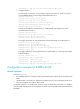
B-DDR configuration example
Network requirements
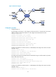
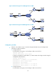
As shown in Figure 42:
• On Router A, interface Dialer 0 is assigned an IP address 100.1.1.1/24 and Dialer 1 an IP address
122.1.1.1 /24 .
• On Router B, interface Dialer 0 is assigned an IP address 100.1.1.2/24.
• On Router C, interface Dialer 0 is assigned an IP address 122.1.1.2/24.
• The Dialer 0 interfaces on Router A and Router B are located on the same network segment. The
Dialer 1 interface on Router A and the Dialer 0 interface on Router C are also located on the same
network segment.
Configure B-DDR to allow Router A to call Router B and Router C from multiple interfaces, but disable
Router B and Router C from calling each other.