
HP MSR2000/3000/4000 Router Series Layer 2 - WAN Configuration Guide

21
# After the configuration is complete, display summary information about Serial 2/0 on Router B.
[RouterB-Serial2/0] display interface serial 2/0 brief
Brief information on interface(s) under route mode:
Link: ADM - administratively down; Stby - standby
Protocol: (s) - spoofing
Interface Link Protocol Main IP Description
S2/0 UP UP 200.1.1.10
The output shows Serial 2/0 obtains IP address 200.1.1.10 through PPP negotiation.
# Ping Serial 2/0 of Router A from Router B.
[RouterB-Serial2/0] ping 200.1.1.1
Ping 200.1.1.1 (200.1.1.1): 56 data bytes, press escape sequence to break
56 bytes from 200.1.1.1: icmp_seq=0 ttl=128 time=3.197 ms
56 bytes from 200.1.1.1: icmp_seq=1 ttl=128 time=2.594 ms
56 bytes from 200.1.1.1: icmp_seq=2 ttl=128 time=2.739 ms
56 bytes from 200.1.1.1: icmp_seq=3 ttl=128 time=1.738 ms
56 bytes from 200.1.1.1: icmp_seq=4 ttl=128 time=1.744 ms
--- Ping statistics for 200.1.1.1 ---
5 packet(s) transmitted, 5 packet(s) received, 0.0% packet loss
round-trip min/avg/max/std-dev = 1.738/2.402/3.197/0.576 ms
The output shows Serial 2/0 of Router A can be pinged.
Specifying an address pool on the server interface
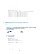
Network requirements
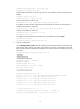
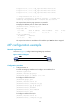
As shown in Figure 7, configure Router A to allocate an IP address from the address pool on Serial 2/0
of Router A to Serial 2/0 of Router B through PPP negotiation..
Figure 7 Network diagram
Configuration procedure
1. Configure Router A:
# Configure an address pool aaa that contains IP addresses 200.1.1.10 through 200.1.1.20 for
the group AAA.
<RouterA> system-view
[RouterA] ip pool aaa 200.1.1.10 200.1.1.20 group AAA
# Configure Serial 2/0 to assign an IP address from the address pool aaa to the peer interface.
[RouterA] interface serial 2/0
[RouterA-Serial2/0] remote address pool aaa
# Configure an IP address for Serial 2/0.
[RouterA-Serial2/0] ip address 200.1.1.1 16
2. Configure Router B:
# Enable IP address negotiation on Serial 2/0.