
HP MSR2000/3000/4000 Router Series Layer 2 - WAN Configuration Guide

72
[RouterB-Serial1/0:15] dialer circular enable
[RouterB-Serial1/0:15] dialer route ip 202.38.154.1 8810152
[RouterB-Serial1/0:15] dialer-group 1
3. Verify the configuration:
a. Ping 202.38.154.2 on Router A to trigger a call. The log shows that the line for a B channel
on E1 1/0 is up.
b. Ping 202.38.154.2, and the attempt succeeds. No packet is lost.
Configuration example for connecting devices through ISDN
BRI lines running NI
Network requirements
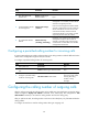
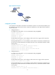
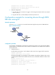
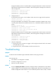
As shown in Figure 31, Router A is connected to Router B through the NI protocol of ISDN BRI lines.
Figure 31 Network diagram
Configuration procedure
In this example, the ISDN BRIs on both Router A and Router B operate in user side mode (the default),
and the interfaces on the device that connect to Router A and Router B in the ISDN network operate in
network side mode.
1. Configure Router A:
# Create dialer access group 1 and configure a dial access rule to trigger calls for IP packets.
<RouterA> system-view
[RouterA] dialer-group 1 rule ip permit
# Assign interface BRI 2/0 an IP address, enable C-DDR on the interface, dial 8810154 to set up
a link for packets destined to host address 202.38.154.2, and add the interface to dialer access
group 1.
[RouterA] interface bri 2/0
[RouterA-Bri2/0] ip address 202.38.154.1 255.255.0.0
[RouterA-Bri2/0] dialer circular enable
[RouterA-Bri2/0] dialer route ip 202.38.154.2 8810154
[RouterA-Bri2/0] dialer-group 1