
HP MSR2000/3000/4000 Router Series Layer 3 - IP Services Command Reference


320
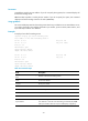
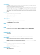
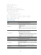
Line protocol state: UP
Description: Tunnel1 Interface
Bandwidth: 64kbps
Maximum Transmit Unit: 1476
Internet Address is 10.1.2.1/24 Primary
Tunnel source 2002::1:1, destination 2001::2:1
Tunnel keepalive enabled, Period(50 s), Retries(3)
Tunnel TOS 0xC8, Tunnel TTL 255
Tunnel protocol/transport GRE/IPv6
GRE key value is 1
Checksumming of GRE packets disabled
Last clearing of counters: Never
Last 300 seconds input rate: 0 bytes/sec, 0 bits/sec, 0 packets/sec
Last 300 seconds output rate: 0 bytes/sec, 0 bits/sec, 0 packets/sec
Input: 0 packets, 0 bytes, 0 drops
Output: 0 packets, 0 bytes, 0 drops
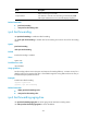
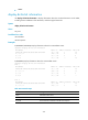
Table 83 Command output
Field Descri
p
tion
Tunnel1 Information about the tunnel interface Tunnel1.
Current state
Physical state of the tunnel interface:
• Administratively DOWN—The interface has been shut down by the
shutdown command.
• DOWN—The interface is administratively up but its physical state is
down.
• UP—Both the administrative and physical states of the interface are
up.
Line protocol state
Link layer protocol state of the tunnel interface. The value is determined
by the parameter negotiation on the link layer.
• UP—The protocol state of the interface is up.
• UP (spoofing)—The link protocol state of the interface is up, but the
link is temporarily set up on demand or does not exist. This attribute
is available for null interfaces and loopback interfaces.
• DOWN—The protocol state of the interface is down.
Description Description of the tunnel interface.
Bandwidth Intended bandwidth for the tunnel interface.
Maximum Transmit Unit MTU of the tunnel interface.
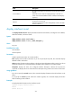
Internet Address
IP address of the tunnel interface.
If no IP address is assigned to the interface, this field displays Internet
protocol processing: disabled, and the tunnel interface cannot process
packets.
Primary indicates it is the primary IP address of the interface.
Tunnel source Source address of the tunnel.
destination Destination address of the tunnel.