
HP MSR2000/3000/4000 Router Series Layer 3 - IP Services Configuration Guide

95
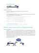
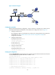
Figure 37 Network diagram
Configuration procedure
Before performing the following configuration, ,make sure Device A, the DNS server, and the host can
reach each other and the IPv6 addresses of the interfaces are configured as shown in Figure 37.
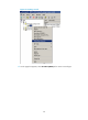
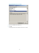
1. Conf
igure the DNS server:
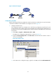
The configuration might vary with DNS servers. When a PC running Windows Server 2000 acts
as the DNS server, see "Dynamic domain name resolution c
onfiguration example" for
configuration information.
2. Configure the DNS proxy:
# Specify the DNS server 4.1.1.1.
<DeviceA> system-view
[DeviceA] dns server 4.1.1.1
# Enable DNS proxy.
[DeviceA] dns proxy enable
3. Configure the DNS client:
<DeviceB> system-view
# Specify the DNS server 2.1.1.2.
[DeviceB] dns server 2.1.1.2
Verifying the configuration
# Use the ping host.com command on Device B to verify the connection between the device and the host
is normal and that the translated destination IP address is 3.1.1.1.
[DeviceB] ping host.com
Ping host.com (3.1.1.1): 56 data bytes, press escape sequence to break
56 bytes from 3.1.1.1: icmp_seq=0 ttl=255 time=1.000 ms
56 bytes from 3.1.1.1: icmp_seq=1 ttl=255 time=1.000 ms
56 bytes from 3.1.1.1: icmp_seq=2 ttl=255 time=1.000 ms
56 bytes from 3.1.1.1: icmp_seq=3 ttl=255 time=1.000 ms
56 bytes from 3.1.1.1: icmp_seq=4 ttl=255 time=2.000 ms
--- Ping statistics for host.com ---
5 packet(s) transmitted, 5 packet(s) received, 0.0% packet loss