
HP MSR2000/3000/4000 Router Series Layer 3 - IP Services Configuration Guide

7
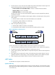
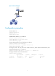
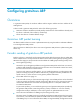
Figure 3 Network diagram
Configuration procedure
# Create VLAN 10.
<Switch> system-view
[Switch] vlan 10
[Switch-vlan10] quit
# Add interface Ethernet 1/1 to VLAN 10.
[Switch] interface ethernet 1/1
[Switch-Ethernet1/1] port access vlan 10
[Switch-Ethernet1/1] quit
# Create VLAN-interface 10 and configure its IP address.
[Switch] interface vlan-interface 10
[Switch-vlan-interface10] ip address 192.168.1.2 8
[Switch-vlan-interface10] quit
# Configure a static ARP entry that has IP address 192.168.1.1, MAC address 00e0-fc01-0000, and
output interface Ethernet 1/1 in VLAN 10.
[Switch] arp static 192.168.1.1 00e0-fc01-0000 10 ethernet 1/1
# Display information about static ARP entries.
[Switch] display arp static
Type: S-Static D-Dynamic M-Multiport I-Invalid
IP Address MAC Address VLAN Interface Aging Type
192.168.1.1 00e0-fc01-0000 10 Eth1/1 N/A S