
HP MSR2000/3000/4000 Router Series Layer 3 - IP Services Configuration Guide

190
Configuring the maximum number of attempts to send an NS
message for DAD
An interface sends an NS message for DAD after obtaining an IPv6 address. If the interface does not
receive a response within the time specified by the ipv6 nd ns retrans-timer command, it sends an NS
message again. If the interface still does not receive a response after the number of attempts reaches the
threshold specified by the ipv6 nd dad attempts command, it considers the address is usable.
To configure the attempts to send an NS message for DAD:
Ste
p
Command
Remarks
1. Enter system view.
system-view N/A
2. Enter interface view.
interface interface-type
interface-number
N/A
3. Configure the number of
attempts to send an NS
message for DAD.
ipv6 nd dad attempts value
The default setting is 1. When the
value argument is set to 0, DAD is
disabled.
Enabling ND proxy
About ND proxy
ND proxy enables a device to answer an NS message requesting the hardware address of a host on
another network. With ND proxy, hosts on different broadcast domains can communicate with each
other as they would on the same network.
ND proxy includes common ND proxy and local ND proxy.
• Common ND proxy
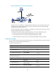
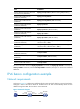
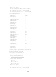
As shown in Figure 73, Ethernet 1/1 with IPv6 address 4:1::99/64 and Ethernet 1/2 with IPv6
address 4:2::99/64 belong to different
subnets. Host A and Host B reside on the same network
but in different broadcast domains.
Figure 73 Application environment of ND proxy
Because Host A's IPv6 address is on the same subnet as Host B's, Host A directly sends an NS
message to obtain Host B's MAC address. However, Host B cannot receive the NS message
because they belong to different broadcast domains.
To solve this problem, enable common ND proxy on Ethernet 1/1 and Ethernet 1/2 of the router.
The router replies to the NS message from Host A, and forwards packets from other hosts to Host
B.
• Local ND proxy
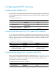
As shown in Figure 74, both Host A and Host B belong to VLAN 2, but they conn
ect to Ethernet
1/3 and Ethernet 1/1 respectively, which are isolated at Layer 2.
4:1::100/16
4:2::100/16
Eth1/1
4:1::99/64
Eth1/2
4:2::99/64
Host A
Host B
Router