
HP MSR2000/3000/4000 Router Series Layer 3 - IP Services Configuration Guide


17
ARP fast-reply configuration example
Network requirements
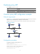
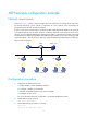
As shown in Figure 5, Client 1, Client 2 through Client 100, and Client 101 through Client 200 access
the network through AP 1, AP 2 and AP 3, respectively. AP 1, AP 2 and AP 3 are connected to AC
through the switch. APs are connected to VLAN 2.
If Client 1 wants to access Client 200, it broadcasts an ARP request and the AC sends it to AP 2 and AP
3. As ARP broadcasts occupy tunnel resources excessively especially when many APs exist on the
network, you can enable the ARP fast-reply mechanism for VLAN 1. In the following example, Client 200
has obtained an IP address through DHCP. With ARP fast-reply enabled, the AC, upon receiving an ARP
request from Client 1, directly returns an ARP reply without broadcasting the ARP request to other APs.
Figure 5 Network diagram
Configuration procedure
1. Configure basic functions on the AC:
a. Enable WLAN, create a WLAN-ESS interface.
b. Configure a WLAN service template.
c. Bind the WLAN-ESS interface to this service template.
d. Configure the APs on AC.
For more information about the configuration, see WLAN Configuration Guide.
2. Enable ARP snooping on the AC.
[AC] arp snooping enable
3. Enable ARP fast-reply for VLAN 1 on the AC.
[AC] vlan 1
[AC-vlan1] arp fast-reply enable
AP 1 AP 2
AP 3
DHCP serverAC Switch
…… ……
Client 1 Client 2 ~ Client 100 Client 101 ~ Client 200