HP MSR2000/3000/4000 Router Series MPLS Configuration Guide (V7) Part number: 5998-3994 Software version: CMW710-R0007P02 Document version: 6PW100-20130927
Legal and notice information © Copyright 2013 Hewlett-Packard Development Company, L.P. No part of this documentation may be reproduced or transmitted in any form or by any means without prior written consent of Hewlett-Packard Development Company, L.P. The information contained herein is subject to change without notice.
Contents Configuring basic MPLS ·············································································································································· 1 Overview············································································································································································ 1 Basic concepts ·········································································································································
LDP LSP configuration example ···························································································································· 28 Label acceptance control configuration example ······························································································ 33 Label advertisement control configuration example ·························································································· 37 Configuring MPLS TE ············································
CRLSP setup procedure ········································································································································· 91 RSVP refresh mechanism······································································································································· 91 RSVP authentication ·············································································································································· 92 RSVP GR ··············
Redistributing the loopback interface route ······································································································ 141 Creating a sham link ··········································································································································· 141 Configuring routing on an MCE ································································································································· 142 Configuring routing between an M
Configuring MPLS OAM for LSP tunnels ···················································································································· 278 Configuring MPLS ping for LSPs ························································································································ 278 Configuring MPLS traceroute for LSPs ··············································································································· 278 Configuring periodic MPLS traceroute for LSPs
Configuring basic MPLS Multiprotocol Label Switching (MPLS) provides connection-oriented label switching over connectionless IP backbone networks. It integrates both the flexibility of IP routing and the simplicity of Layer 2 switching. Overview MPLS has the following advantages: • High speed and efficiency—MPLS uses short- and fixed-length labels to forward packets, avoiding complicated routing table lookups. • Multiprotocol support—MPLS resides between the link layer and the network layer.
LSR A router that performs MPLS forwarding is a label switching router (LSR). LSP A label switched path (LSP) is the path along which packets of a FEC travel through an MPLS network. An LSP is a unidirectional packet forwarding path. Two neighboring LSRs are called the "upstream LSR" and "downstream LSR" along the direction of an LSP. In Figure 2, LSR B is the downstream LSR of LSR A, and LSR A is the upstream LSR of LSR B.
An MPLS network comprises the following types of LSRs: • Ingress LSR—Ingress LSR of packets. It labels packets entering into the MPLS network. • Transit LSR—Intermediate LSRs in the MPLS network. The transit LSRs on an LSP forward packets to the egress LSR according to labels. • Egress LSR—Egress LSR of packets. It removes labels from packets and forwards the packets to their destination networks. LSP establishment LSPs include static and dynamic LSPs.
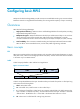
MPLS forwarding Figure 5 MPLS forwarding FIB table LFIB table Dest Out label Nexthop Out int 40 Router C Eth1/2 10.1.0.0 LFIB table In label 40 IP:10.1.1.1 40 Eth1/1 Router A Oper Swap Oper Pop Out label Nexthop -Router E Out int Eth1/2 Out label Nexthop Out int 50 Router D Eth1/2 IP:10.1.1.1 Eth1/2 Router B Ingress In label 50 50 Eth1/1 IP:10.1.1.1 IP:10.1.1.
packet matches an LFIB entry comprising the explicit null label, the penultimate hop replaces the value of the top label with value 0, and forwards the packet to the egress node. The egress node gets the TC information, pops the label of the packet, and forwards the packet.
Configuring MPLS MTU MPLS inserts the label stack between the link layer header and network layer header of each packet. To make sure the size of MPLS labeled packets is smaller than the MTU of an interface, configure an MPLS MTU on the interface. MPLS compares each MPLS packet against the interface MPLS MTU.
If the egress advertises a non-null label (normal label), the penultimate hop swaps the top label of a matching packet with the specific label assigned by the egress. • Configuration guidelines If the penultimate hop supports PHP, HP recommends that you configure the egress to advertise an implicit null label to the penultimate hop.
Figure 6 TTL propagation When TTL propagation is disabled, the ingress node sets the label TTL to 255. Each LSR on the LSP decreases the label TTL value by 1. The LSR that pops the label does not change the IP TTL value when popping the label. Therefore, the MPLS backbone nodes are invisible to user networks, and the IP tracert facility cannot show the real path in the MPLS network.
Enabling sending of MPLS TTL-expired messages This feature enables an LSR to generate an ICMP TTL-expired message upon receiving an MPLS packet with a TTL of 1. If the MPLS packet has only one label, the LSR sends the ICMP TTL-expired message back to the source through IP routing. If the MPLS packet has multiple labels, the LSR sends it along the LSP to the egress, which then sends the message back to the source. To enable sending of MPLS TTL-expired messages: Step Command Remarks 1. Enter system view.
Task Command Display ILM entries (MSR2000/MSR3000). display mpls forwarding ilm [ label ] Display ILM entries (MSR4000). display mpls forwarding ilm [ label ] slot slot-number Display NHLFE entries (MSR2000/MSR3000). display mpls forwarding nhlfe [ nid ] Display NHLFE entries (MSR4000).
Configuring a static LSP Overview A static label switched path (LSP) is established by manually specifying the incoming label and outgoing label on each node (ingress, transit, or egress node) of the forwarding path. Static LSPs consume fewer resources, but they cannot automatically adapt to network topology changes. Therefore, static LSPs are suitable for small and stable networks with simple topologies.
Step Command Remarks 2. Configure the ingress node of the static LSP. static-lsp ingress lsp-name destination dest-addr { mask | mask-length } { nexthop next-hop-addr | outgoing-interface interface-type interface-number } out-label out-label If you specify a next hop for the static LSP, make sure the ingress node has an active route to the specified next hop address. 3. Configure the transit node of the static LSP.
• A route to the destination address of the LSP must be available on the ingress node, but it is not needed on transit and egress nodes. Therefore, you do not need to configure a routing protocol to ensure IP connectivity among all routers. Configuration procedure 1. Configure IP addresses for all interfaces, including the loopback interfaces, as shown in Figure 8. (Details not shown.) 2.
[RouterB] static-lsp transit CtoA in-label 40 nexthop 10.1.1.1 out-label 70 # Configure the LSP egress node, Router A. [RouterA] static-lsp egress CtoA in-label 70 Verifying the configuration # Use the display mpls static-lsp command on each router to view information about static LSPs. Take Router A as an example: [RouterA] display mpls static-lsp Total: 2 Name FEC In/Out Label Nexthop/Out Interface State AtoC 21.1.1.0/24 NULL/30 10.1.1.
Configuring LDP Overview The Label Distribution Protocol (LDP) dynamically distributes FEC-label mapping information between LSRs to establish LSPs. Terminology LDP session Two LSRs establish a TCP-based LDP session to exchange FEC-label mappings. LDP peer Two LSRs that use LDP to exchange FEC-label mappings are LSR peers. Label spaces and LDP identifiers Label spaces include the following types: • Per-interface label space—Each interface uses a single, independent label space.
• Advertisement messages—Create, alter, and remove FEC-label mappings, such as Label Mapping messages used to advertise FEC-label mappings. • Notification messages—Provide advisory information and notify errors, such as Notification messages. LDP uses UDP to transport discovery messages for efficiency, and uses TCP to transport session, advertisement, and notification messages for reliability.
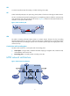
Figure 9 Dynamically establishing an LSP Label distribution and control Label advertisement modes Figure 10 Label advertisement modes DU mode Ingress 2) Unsolicitely distributes a label mapping for the FEC to the upstream. 1) Unsolicitely distributes a label mapping for a FEC to the upstream. Transit Egress 1) Sends a label request for a FEC to the downstream. 2) Sends a label request for the FEC to the downstream.
Label distribution control LDP controls label distribution in one of the following ways: • Independent label distribution—Distributes a FEC-label mapping to an upstream LSR at any time. An LSR might distribute a mapping for a FEC to its upstream LSR before it receives a label mapping for that FEC from its downstream LSR.
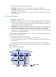
LDP GR LDP GR overview LDP Graceful Restart enables an LSR to retain MPLS forwarding entries during an LDP restart, ensuring continuous MPLS forwarding. Figure 12 LDP GR As shown in Figure 12, GR defines the following roles: • GR restarter—An LSR that performs GR. It must be GR-capable. • GR helper—A neighbor LSR that helps the GR restarter to complete GR. The device can act as a GR restarter or a GR helper.
restarter goes down, it marks the FEC-label mappings learned from the session as stale and starts the Reconnect timer received from the GR restarter. 3. After LDP completes restart, the GR restarter re-establishes an LDP session with the GR helper. If the LDP session is not set up before the Reconnect timer expires, the GR helper deletes the stale FEC-label mappings and the corresponding MPLS forwarding entries.
Enabling LDP To enable LDP, you must enable LDP globally, and then enable LDP on relevant interfaces or configure IGP to automatically enable LDP on those interfaces. Enabling LDP globally Step 1. Enter system view. Command Remarks system-view N/A • Enable LDP for the local node and 2. Enable LDP for the local node or for a VPN. enter LDP view: mpls ldp • Enable LDP for a VPN and enter By default, LDP is disabled. LDP-VPN instance view: a. mpls ldp b. vpn-instance vpn-instance-name 3.
Step Configure the Link Hello interval. 4. Command Remarks mpls ldp timer hello-interval interval By default, the Link Hello interval is five seconds. Configuring LDP session parameters This task configures the following LDP session parameters: • Keepalive hold time and Keepalive interval. • LDP transport address—IP address for establishing TCP connections.
The LDP backoff mechanism can mitigate this problem by using an initial delay timer and a maximum delay timer. After LDP fails to establish a session with a peer LSR for the first time, LDP does not start an attempt until the initial delay timer expires. If the session setup fails again, LDP waits for two times the initial delay before the next attempt, and so forth until the maximum delay time is reached. After that, the maximum delay time will always take effect.
Use only host routes with a 32-bit mask to establish LSPs. • By default, LDP uses only host routes with a 32-bit mask to establish LSPs. The other two methods can result in more LSPs than the default policy. To change the policy, be sure that the system resources and bandwidth resources are sufficient. Configure an LSP generation policy: Step 1. Enter system view. Command Remarks system-view N/A • Enter LDP view: 2. Enter LDP view or enter LDP-VPN instance view.
Figure 14 Label advertisement control diagram A label advertisement policy on an LSR and a label acceptance policy on its upstream LSR can achieve the same purpose. HP recommends that you use label advertisement policies to reduce network load if downstream LSRs support label advertisement control. Before you configure an LDP label advertisement policy, create an IP prefix list. For information about IP prefix list configuration, see Layer 3—IP Routing Configuration Guide.
Figure 15 Label acceptance control diagram D o be la er s ilt g t f pin no ap m l A label advertisement policy on an LSR and a label acceptance policy on its upstream LSR can achieve the same purpose. HP recommends using the label advertisement policy to reduce network load. You must create an IP prefix list before you configure a label acceptance policy. For information about IP prefix list configuration, see Layer 3—IP Routing Configuration Guide.
Step Command Remarks • Enter LDP view: 2. Enter LDP view or enter LDP-VPN instance view. mpls ldp • Enter LDP-VPN instance view: N/A a. mpls ldp b. vpn-instance vpn-instance-name By default, loop detection is disabled. After loop detection is enabled, the device uses both the maximum hop count and the path vector methods to detect loops. 3. Enable loop detection. loop-detect 4. Specify the maximum hop count. maxhops hop-number By default, the maximum hop count is 32. 5.
Task Command Reset LDP sessions. reset mpls ldp [ vpn-instance vpn-instance-name ] [ peer peer-id ] Enabling SNMP notifications for LDP This feature enables generating SNMP notifications for LDP upon LDP session changes, as defined in RFC 3815. The generated SNMP notifications are sent to the SNMP module. To enable SNMP notifications for LDP: Step Command Remarks 1. Enter system view. system-view N/A 2. Enable SNMP notifications for LDP.
Configure LDP to establish LSPs between Router A and Router C, so subnets 11.1.1.0/24 and 21.1.1.0/24 can reach each other over MPLS. Configure LDP to establish LSPs for only destinations 1.1.1.9/32, 2.2.2.9/32, 3.3.3.9/32, 11.1.1.0/24, and 21.1.1.0/24 on Router A, Router B, and Router C. Figure 16 Network diagram Configuration considerations • LDP assigns labels according to routing information. To establish LDP LSPs, you must configure a routing protocol to make sure the LSRs can reach each other.
[RouterC] ospf [RouterC-ospf-1] area 0 [RouterC-ospf-1-area-0.0.0.0] network 3.3.3.9 0.0.0.0 [RouterC-ospf-1-area-0.0.0.0] network 20.1.1.0 0.0.0.255 [RouterC-ospf-1-area-0.0.0.0] network 21.1.1.0 0.0.0.255 [RouterC-ospf-1-area-0.0.0.0] quit [RouterC-ospf-1] quit # Verify that the routers have learned the routes to each other. For example, on Router A: [RouterA] display ip routing-table Destinations : 21 3. Routes : 21 Destination/Mask Proto 0.0.0.0/32 1.1.1.
[RouterB-Serial2/0] mpls enable [RouterB-Serial2/0] mpls ldp enable [RouterB-Serial2/0] quit [RouterB] interface serial 2/1 [RouterB-Serial2/1] mpls enable [RouterB-Serial2/1] mpls ldp enable [RouterB-Serial2/1] quit # Configure Router C. [RouterC] mpls lsr-id 3.3.3.9 [RouterC] mpls ldp [RouterC-ldp] quit [RouterC] interface serial 2/0 [RouterC-Serial2/0] mpls enable [RouterC-Serial2/0] mpls ldp enable [RouterC-Serial2/0] quit 4.
Verifying the configuration # Execute the display mpls ldp lsp command on each router to view the LDP LSP information. For example, on Router A: [RouterA] display mpls ldp lsp Status Flags: * - stale, L - liberal Statistics: FECs: 5 Ingress LSPs: 3 FEC In/Out Label 1.1.1.9/32 3/- Transit LSPs: 3 Egress LSPs: 2 Nexthop OutInterface -/3 10.1.1.2 S2/0 1279/3 10.1.1.2 S2/0 -/1278 10.1.1.2 S2/0 1278/1278 10.1.1.2 S2/0 -/1276 10.1.1.2 S2/0 1276/1276 10.1.1.2 S2/0 -/1279(L) 2.2.2.
Label acceptance control configuration example Network requirements Two links, Router A—Router B—Router C and Router A—Router D—Router C, exist between subnets 11.1.1.0/24 and 21.1.1.0/24. Configure label acceptance control, so LDP sets up LSPs only on the link Router A—Router B—Router C to forward traffic between subnets 11.1.1.0/24 and 21.1.1.0/24. Figure 17 Network diagram Configuration considerations 1. Configure a routing protocol on each router to make sure that the routers can reach each other.
[RouterA] mpls ldp [RouterA-ldp] quit [RouterA] interface serial 2/0 [RouterA-Serial2/0] mpls enable [RouterA-Serial2/0] mpls ldp enable [RouterA-Serial2/0] quit [RouterA] interface serial 2/1 [RouterA-Serial2/1] mpls enable [RouterA-Serial2/1] mpls ldp enable [RouterA-Serial2/1] quit # Configure Router B. system-view [RouterB] mpls lsr-id 2.2.2.
[RouterD-Serial2/1] quit 4. Configure LSP generation policies: # On Router A, create IP prefix list routera, and configure LDP to use only the routes permitted by the prefix list to establish LSPs. [RouterA] ip prefix-list routera index 10 permit 11.1.1.0 24 [RouterA] ip prefix-list routera index 20 permit 21.1.1.
# On Router C, create an IP prefix list prefix-from-d that denies subnet 11.1.1.0/24. Router A uses this list to filter FEC-label mappings received from Router D. [RouterC] ip prefix-list prefix-from-d index 10 deny 11.1.1.0 24 # On Router C, configure label acceptance policies to filter FEC-label mappings received from Router B and Router D. [RouterC] mpls ldp [RouterC-ldp] accept-label peer 2.2.2.9 prefix-list prefix-from-b [RouterC-ldp] accept-label peer 4.4.4.
--- FEC: 11.1.1.0/24 ping statistics --5 packets transmitted, 5 packets received, 0.0% packet loss round-trip min/avg/max = 1/1/1 ms Label advertisement control configuration example Network requirements Two links, Router A—Router B—Router C and Router A—Router D—Router C, exist between subnets 11.1.1.0/24 and 21.1.1.0/24. Configure label advertisement control, so LDP sets up LSPs only on the link Router A—Router B—Router C to forward traffic between subnets 11.1.1.0/24 and 21.1.1.0/24.
3. Enable MPLS and LDP: # Configure Router A. system-view [RouterA] mpls lsr-id 1.1.1.9 [RouterA] mpls ldp [RouterA-ldp] quit [RouterA] interface serial 2/0 [RouterA-Serial2/0] mpls enable [RouterA-Serial2/0] mpls ldp enable [RouterA-Serial2/0] quit [RouterA] interface serial 2/1 [RouterA-Serial2/1] mpls enable [RouterA-Serial2/1] mpls ldp enable [RouterA-Serial2/1] quit # Configure Router B. system-view [RouterB] mpls lsr-id 2.2.2.
[RouterD-Serial2/0] mpls ldp enable [RouterD-Serial2/0] quit [RouterD] interface serial 2/1 [RouterD-Serial2/1] mpls enable [RouterD-Serial2/1] mpls ldp enable [RouterD-Serial2/1] quit 4. Configure LSP generation policies: # On Router A, create IP prefix list routera, and configure LDP to use only the routes permitted by the prefix list to establish LSPs. [RouterA] ip prefix-list routera index 10 permit 11.1.1.0 24 [RouterA] ip prefix-list routera index 20 permit 21.1.1.
# On Router C, create an IP prefix list prefix-to-b that permits subnet 21.1.1.0/24. Router C uses this list to filter FEC-label mappings advertised to Router B. [RouterC] ip prefix-list prefix-to-b index 10 permit 21.1.1.0 24 # On Router C, create an IP prefix list peer-b that permits 2.2.2.9/32. Router C uses this list to filter peers. [RouterC] ip prefix-list peer-b index 10 permit 2.2.2.9 32 # On Router C, configure a label advertisement policy to advertise only the label mapping for FEC 21.1.1.
Statistics: FECs: 2 Ingress LSPs: 2 Transit LSPs: 2 Egress LSPs: 0 FEC In/Out Label Nexthop OutInterface 11.1.1.0/24 -/1277 10.1.1.1 S2/0 1277/1277 10.1.1.1 S2/0 -/1149 20.1.1.2 S2/1 1276/1149 20.1.1.2 S2/1 21.1.1.0/24 [RouterC] display mpls ldp lsp Status Flags: * - stale, L - liberal Statistics: FECs: 2 Ingress LSPs: 1 Transit LSPs: 1 Egress LSPs: 1 FEC In/Out Label Nexthop OutInterface 11.1.1.0/24 -/1277 20.1.1.1 S2/0 1148/1277 20.1.1.1 S2/0 21.1.1.
100 bytes from 10.1.1.1: Sequence=2 time=1 ms 100 bytes from 10.1.1.1: Sequence=3 time=1 ms 100 bytes from 10.1.1.1: Sequence=4 time=1 ms 100 bytes from 10.1.1.1: Sequence=5 time=1 ms --- FEC: 11.1.1.0/24 ping statistics --5 packets transmitted, 5 packets received, 0.
Configuring MPLS TE Overview TE and MPLS TE Network congestion can degrade the network backbone performance. It might occur when network resources are inadequate or when load distribution is unbalanced. Traffic engineering (TE) is intended to avoid the latter situation where partial congestion might occur because of improper resource allocation.
1. An IGP advertises TE attributes for links. 2. MPLS TE uses the CSPF algorithm to calculate the shortest path that meets the constraints (such as bandwidth and explicit routing) to the tunnel destination. 3. A label distribution protocol (such as RSVP-TE) advertises labels to establish CRLSPs and reserve bandwidth resources on each node along the calculated path. Dynamic CRLSPs adapt to network changes and support CRLSP backup and fast reroute, but they require complicated configurations.
higher than the holding priority of the existing tunnel. Both setup and holding priorities are in the range of 0 to 7. A smaller value indicates a higher priority. To avoid flapping caused by improper preemptions, the setup priority of a tunnel must not be higher than its holding priority, namely, the setup priority value must be equal to or greater than the holding priority value. • Explicit path Explicit path specifies the nodes to pass and the nodes to not pass for a tunnel.
Make-before-break Make-before-break is a mechanism to change an MPLS TE tunnel with minimum data loss and without using extra bandwidth. In cases of tunnel reoptimization, traffic forwarding is interrupted if the existing CRLSP is removed before a new CRLSP is established. The make-before-break mechanism makes sure that the existing CRLSP is removed after the new CRLSP is established and the traffic is switched to the new CRLSP.
Tunnel reoptimization Tunnel reoptimization allows you to manually or dynamically trigger the ingress node to recalculate a path. If the ingress node recalculates a better path, it creates a new CRLSP, switches traffic from the old CRLSP to the new, and then deletes the old CRLSP. MPLS TE uses the tunnel reoptimization function to implement dynamic CRLSP optimization.
Figure 20 FRR link protection • Node protection—The PLR and the MP are connected through a device and the primary CRLSP traverses this device. When the device fails, traffic is switched to the bypass CRLSP. As shown in Figure 21, the primary CRLSP is Router A—Router B—Router C—Router D—Router E, and the bypass CRLSP is Router B—Router F—Router D. Router C is the protected device.
Basic concepts • CT—Class Type. DS-TE allocates link bandwidth, implements constraint-based routing, and performs admission control on a per class type basis. A given traffic flow belongs to the same CT on all links. • BC—Bandwidth Constraint. BC restricts the bandwidth for one or more CTs. • Bandwidth constraint model—Algorithm for implementing bandwidth constraints on different CTs. A BC model comprises two factors, the maximum number of BCs (MaxBC) and the mappings between BCs and CTs.
Figure 22 RDM bandwidth constraints model In MAM model, a BC constrains the bandwidth for only one CT. This ensures bandwidth isolation among CTs no matter whether preemption is used or not. Compared with RDM, MAM is easier to configure. MAM is suitable for networks where traffic of each CT is stable and no traffic bursts occur. Figure 23 shows an example: • BC 0 is for CT 0. The bandwidth occupied by the traffic of CT 0 cannot exceed BC 0. • BC 1 is for CT 1.
During the delivery of the Resv message, a CRLSP in the other direction is established. The CRLSPs of a bidirectional MPLS TE tunnel established in co-routed mode use the same path. • Associated mode—In this mode, you establish a bidirectional MPLS TE tunnel by binding two unidirectional CRLSPs in opposite directions. The two CRLSPs can be established in different modes and use different paths. For example, one CRLSP is established statically and the other CRLSP is established dynamically by RSVP-TE.
10. On the ingress node of the MPLS TE tunnel, configure RSVP-TE to establish a CRLSP based on the tunnel constraints and link TE attributes. 11. On the ingress node of the MPLS TE tunnel, configure static routing or PBR to direct traffic to the MPLS TE tunnel. You can also configure other MPLS TE functions such as the DS-TE and FRR as needed. To configure MPLS TE, perform the following tasks: Tasks at a glance (Required.) Enabling MPLS TE (Required.) Configuring a tunnel interface (Optional.
Step 5. Enable MPLS TE for the interface. Command Remarks mpls te enable By default, MPLS TE is disabled on an interface. Configuring a tunnel interface To configure an MPLS TE tunnel, you must create an MPLS TE tunnel interface and enter tunnel interface view. All MPLS TE tunnel attributes are configured in tunnel interface view. For more information about tunnel interfaces, see Layer 3—IP Services Configuration Guide. Perform this task on the ingress node of the MPLS TE tunnel.
Table 1 Default TE classes in IETF mode TE Class CT Priority 0 0 7 1 1 7 2 2 7 3 3 7 4 0 0 5 1 0 6 2 0 7 3 0 Configuring an MPLS TE tunnel to use a static CRLSP To configure an MPLS TE tunnel to use a static CRLSP, establish the static CRLSP, specify the MPLS TE tunnel establishment mode as static, and configure the MPLS TE tunnel to reference the static CRLSP. Other configurations, such as tunnel constraints, IGP extension and CSPF, are not needed.
You must configure the IGP TE extension to form a TEDB. Otherwise, the path is created based on IGP routing rather than computed by CSPF. Configuration task list To establish an MPLS TE tunnel by using a dynamic CRLSP, perform the following tasks: Tasks at a glance (Required.) Configuring MPLS TE attributes for a link (Required.) Configuring MPLS TE tunnel constraints (Required.) Establishing an MPLS TE tunnel by using RSVP-TE (Optional.) Controlling CRLSP path selection (Optional.
Step Command Remarks • Configure the maximum reservable bandwidth of the link (BC 0) and BC 1 in RDM model of the prestandard DS-TE: mpls te max-reservable-bandwidth bandwidth-value [ bc1 bc1-bandwidth ] • Configure the maximum reservable 4. bandwidth of the link and the BCs in MAM model of the IETF DS-TE: mpls te max-reservable-bandwidth mam bandwidth-value { bc0 bc0-bandwidth | bc1 bc1-bandwidth | bc2 bc2-bandwidth | bc3 bc3-bandwidth } * Configure the maximum reservable bandwidth.
Step Configure an affinity for the MPLS TE tunnel. 3. Command Remarks mpls te affinity-attribute attribute-value [ mask mask-value ] By default, the affinity is 0x00000000, and the mask is 0x00000000. The default affinity matches all link attributes. Configuring a setup priority and a holding priority for an MPLS TE tunnel Step Command Remarks 1. Enter system view. system-view N/A 2. Enter MPLS TE tunnel interface view. interface tunnel tunnel-number [ mode mpls-te ] N/A 3.
Step 7. Configure the MPLS TE tunnel interface to use the explicit path, and specify a preference value for the explicit path. Command Remarks mpls te path preference value explicit-path path-name By default, MPLS TE uses the calculated path to establish a CRLSP. Establishing an MPLS TE tunnel by using RSVP-TE Before you configure this task, you must use the rsvp command and the rsvp enable command to enable RSVP on all nodes and interfaces that the MPLS TE tunnel traverses.
Step Command Remarks Specify the metric type to use when no metric type is explicitly configured for a tunnel. path-metric-type igp Execute this command on the ingress node of an MPLS TE tunnel. 4. Return to system view. quit N/A 5. Enter MPLS TE tunnel interface view. interface tunnel tunnel-number [ mode mpls-te ] N/A 3. 6. 7. Specify the metric type for path selection. mpls te path-metric-type igp Return to system view.
Step (Optional.) Immediately reoptimize all MPLS TE tunnels that are enabled with the tunnel reoptimization function. 5. Command Remarks mpls te reoptimization N/A Configuring TE flooding thresholds and interval When the bandwidth of an MPLS TE link changes, IGP floods the new bandwidth information, so the ingress node can use CSPF to recalculate the path.
Step Command Remarks 1. Enter system view. system-view N/A 2. Enter MPLS TE tunnel interface view. interface tunnel tunnel-number [ mode mpls-te ] N/A 3. Record routes or record both routes and labels. • To record routes: By default, both route recording and label recording are disabled.
Step Command Remarks By default, the resource reservation style is SE. 3. Configure the resources reservation style for the tunnel. mpls te resv-style { ff | se } In current MPLS TE applications, tunnels are established usually by using the make-before-break mechanism. Therefore, HP recommends that you use the SE style. Configuring traffic forwarding Perform the tasks in this section on the ingress node of the MPLS TE tunnel.
Step Command Remarks • To apply the policy to the local device: ip local policy-based-route policy-name Apply the PBR policy. 6. Use either method. • To apply the policy to an interface: a. interface interface-type interface-number By default, no policy is applied. b.
To configure an associated bidirectional MPLS TE tunnel: Step Command Remarks 1. Enter system view. system-view N/A 2. Enter MPLS TE tunnel interface view. interface tunnel tunnel-number [ mode mpls-te ] N/A 3. Configure an associated bidirectional MPLS TE tunnel.
• Usually, a bypass tunnel does not forward data when the primary CRLSP works. For a bypass tunnel to also forward data during tunnel protection, you must assign adequate bandwidth to the bypass tunnel. • A bypass tunnel cannot be used for services like VPN. Enabling FRR Perform this task on the ingress node of a primary CRLSP. Step Command Remarks 1. Enter system view. system-view N/A 2. Enter tunnel interface view of the primary CRLSP. interface tunnel tunnel-number [ mode mpls-te ] N/A 3.
Step Command Remarks By default, the bypass tunnel does not provide bandwidth protection. 4. Configure the bandwidth and the CT that the bypass tunnel can protect. mpls te backup bandwidth { bandwidth | { ct0 | ct1 | ct2 | ct3 } { bandwidth | un-limited } } You must execute this command to configure the bandwidth that the bypass tunnel can protect. Otherwise, the primary CRLSP cannot be bound to the bypass tunnel successfully. 5. Return to system view. quit N/A 6.
bypass tunnel because, for example, the reservable bandwidth changes. Therefore, RSVP needs to poll the bypass tunnels periodically to update the optimal bypass tunnel. You can perform this task on the PLR to configure the interval for selecting an optimal bypass tunnel: Step Command Remarks 1. Enter system view. system-view N/A 2. Enter RSVP view. rsvp N/A 3. Configure the interval for selecting an optimal bypass tunnel. fast-reroute timer interval By default, the interval is 300 seconds.
Figure 24 Network diagram Configuration procedure 1. Configure IP addresses and masks for interfaces. (Details not shown.) 2. Configure IS-IS to advertise interface addresses, including the Loopback interface address: # Configure Router A. system-view [RouterA] isis 1 [RouterA-isis-1] network-entity 00.0005.0000.0000.0001.
[RouterC-isis-1] network-entity 00.0005.0000.0000.0003.00 [RouterC-isis-1] quit [RouterC] interface ethernet 1/1 [RouterC-Ethernet1/1] isis enable 1 [RouterC-Ethernet1/1] quit [RouterC] interface loopback 0 [RouterC-LoopBack0] isis enable 1 [RouterC-LoopBack0] quit After the previous configuration, execute the display ip routing-table command on each router. You can see that the routers have learned the routes to one another, including the routes to the Loopback interfaces. 3.
[RouterA-Tunnel0] mpls te signaling static [RouterA-Tunnel0] quit 5. Create a static CRLSP: # Configure Router A as the ingress node of the static CRLSP, and specify the next hop address as 2.1.1.2 and outgoing label as 20. [RouterA] static-cr-lsp ingress static-cr-lsp-1 nexthop 2.1.1.2 out-label 20 # On Router A, configure tunnel 0 to reference the static CRLSP static-cr-lsp-1.
Ingress LSR ID : 1.1.1.1 Egress LSR ID : 3.3.3.
Establishing an inter-AS MPLS TE tunnel with RSVP-TE Network requirements Router A and Router B are in AS 100. Router C and Router D are in AS 200. AS 100 and AS 200 use OSPF as the IGP. Establish an EBGP connection between ASBRs Router B and Router C. Redistribute BGP routes into OSPF and OSPF routes into BGP, so that AS 100 and AS 200 can reach each other. Establish an MPLS TE tunnel from Router A to Router D. The tunnel requires a bandwidth of 2000 kbps.
[RouterB] ospf [RouterB-ospf-1] import-route direct [RouterB-ospf-1] import-route bgp [RouterB-ospf-1] area 0 [RouterB-ospf-1-area-0.0.0.0] network 10.1.1.0 0.0.0.255 [RouterB-ospf-1-area-0.0.0.0] network 2.2.2.9 0.0.0.0 [RouterB-ospf-1-area-0.0.0.0] quit [RouterB-ospf-1] quit # Configure Router C. system-view [RouterC] ospf [RouterC-ospf-1] import-route direct [RouterC-ospf-1] import-route bgp [RouterC-ospf-1] area 0 [RouterC-ospf-1-area-0.0.0.0] network 30.1.1.0 0.0.0.
[RouterB-bgp-ipv4] import-route direct [RouterB-bgp-ipv4] quit [RouterB-bgp] quit # Configure Router C. [RouterC] bgp 200 [RouterC-bgp] peer 20.1.1.1 as-number 100 [RouterC-bgp] ipv4-family unicast [RouterC-bgp-ipv4] peer 20.1.1.1 enable [RouterC-bgp-ipv4] import-route ospf [RouterC-bgp-ipv4] import-route direct [RouterC-bgp-ipv4] quit [RouterC-bgp] quit # After the previous configuration, execute the display ip routing-table command on each router.
[RouterB] interface ethernet 1/1 [RouterB-Ethernet1/1] mpls enable [RouterB-Ethernet1/1] mpls te enable [RouterB-Ethernet1/1] rsvp enable [RouterB-Ethernet1/1] quit [RouterB] interface pos 5/0 [RouterB-POS5/0] mpls enable [RouterB-POS5/0] mpls te enable [RouterB-POS5/0] rsvp enable [RouterB-POS5/0] quit # Configure Router C. [RouterC] mpls lsr-id 3.3.3.
[RouterA-Ethernet1/1] mpls te max-reservable-bandwidth 5000 [RouterA-Ethernet1/1] quit # Configure the maximum link bandwidth and maximum reservable bandwidth on Router B.
Internet Address is 7.1.1.1/24 Primary Tunnel source unknown, destination 4.4.4.
1.1.1.9/32 Direct 0 0 127.0.0.1 InLoop0 2.2.2.9/32 OSPF 10 1 10.1.1.2 Eth1/1 3.3.3.9/32 O_ASE 150 1 10.1.1.2 Eth1/1 4.4.4.9/32 O_ASE 150 1 10.1.1.2 Eth1/1 7.1.1.0/24 Direct 0 0 7.1.1.1 Tun1 7.1.1.1/32 Direct 0 0 127.0.0.1 InLoop0 10.1.1.0/24 Direct 0 0 10.1.1.1 Eth1/1 10.1.1.1/32 Direct 0 0 127.0.0.1 InLoop0 20.1.1.0/24 O_ASE 1 10.1.1.2 Eth1/1 30.1.1.0/24 Static 1 0 7.1.1.1 Tun1 127.0.0.0/8 Direct 0 0 127.0.0.1 InLoop0 127.0.0.1/32 Direct 0 0 127.
Device Interface IP address Eth1/1 4.1.1.2/24 Device Interface IP address Configuration procedure 1. Configure IP addresses and masks for interfaces. (Details not shown.) 2. Configure IS-IS to advertise interface addresses, including the Loopback interface address. (Details not shown.) 3. Configure an LSR ID, and enable MPLS, MPLS TE, RSVP-TE, and CSPF on each router, and enable BFD for RSVP-TE on Router B and Router C: # Configure Router A. system-view [RouterA] mpls lsr-id 1.1.1.
4. Configure an MPLS TE tunnel on Router A, the ingress node of the primary CRLSP: # Configure an explicit path for the primary CRLSP. [RouterA] explicit-path pri-path [RouterA-explicit-path-pri-path] nexthop 2.1.1.2 [RouterA-explicit-path-pri-path] nexthop 3.1.1.2 [RouterA-explicit-path-pri-path] nexthop 4.1.1.2 [RouterA-explicit-path-pri-path] nexthop 4.4.4.
Resv Style : SE Tunnel mode : - Reverse-LSP name : - Reverse-LSP LSR ID : - Reverse-LSP Tunnel ID: - Class Type : CT0 Tunnel Bandwidth : 0 kbps Reserved Bandwidth : 0 kbps Setup Priority : 7 Holding Priority : 7 Affinity Attr/Mask : 0/0 Explicit Path : pri-path : Disabled Backup Explicit Path : Metric Type : IGP Record Route : Disabled Record Label FRR Flag : Enabled Backup Bandwidth Flag: Disabled Backup Bandwidth Type: - 5.
[RouterA] ip route-static 4.1.1.2 24 tunnel 4 preference 1 Verifying the configuration # Execute the display mpls lsp command on each router. You can see the LSP entries. Router B and Router C each have two CRLSPs. The bypass CRLSP backs up the primary CRLSP. [RouterA] display mpls lsp FEC Proto In/Out Label Interface/Out NHLFE 1.1.1.1/4/48960 RSVP -/1245 Eth1/1 2.1.1.2 Local -/- Eth1/1 FEC Proto In/Out Label Interface/Out NHLFE 1.1.1.
Reoptimization : Disabled Reoptimization Freq : - Backup Type : None Backup LSP ID : - Auto Bandwidth : Disabled Auto Bandwidth Freq : - Min Bandwidth : - Max Bandwidth : - Collected Bandwidth : - NOTE: If you execute the display mpls te tunnel-interface command immediately after an FRR, you can see two CRLSPs in up state. This is because FRR uses the make-before-break mechanism to set up a new LSP, and the old LSP is deleted after the new one has been established for a while.
Configuring a static CRLSP Overview A static Constraint-based Routed Label Switched Path (CRLSP) is established by manually specifying the incoming label, outgoing label, and required bandwidth on each node (ingress, transit, or egress node) of the forwarding path. If the device does not have enough bandwidth resources required by a CRLSP, the CRLSP cannot be established. Static CRLSPs consume fewer resources, but they cannot automatically adapt to network topology changes.
Step 1. Enter system view. Command Remarks system-view N/A • Configure the ingress node: Use one command according to the position of a device on the network. static-cr-lsp ingress lsp-name { nexthop next-hop-addr | outgoing-interface interface-type interface-number } out-label out-label-value [ bandwidth [ ct0 | ct1 | ct2 | ct3 ] bandwidth-value ] 2. Create a static CRLSP.
Figure 27 Network diagram Configuration procedure 1. Configure IP addresses and masks for interfaces. (Details not shown.) 2. Configure IS-IS to advertise interface addresses, including the Loopback interface address: # Configure Router A. system-view [RouterA] isis 1 [RouterA-isis-1] network-entity 00.0005.0000.0000.0001.
[RouterC-isis-1] network-entity 00.0005.0000.0000.0003.00 [RouterC-isis-1] quit [RouterC] interface ethernet 1/1 [RouterC-Ethernet1/1] isis enable 1 [RouterC-Ethernet1/1] quit [RouterC] interface loopback 0 [RouterC-LoopBack0] isis enable 1 [RouterC-LoopBack0] quit After the previous configuration, execute the display ip routing-table command on each router. The output shows that the routers have learned the routes to one another, including the routes to the Loopback interfaces. 3.
[RouterA-Tunnel0] mpls te signaling static [RouterA-Tunnel0] quit 5. Create a static CRLSP: # Configure Router A as the ingress node of the static CRLSP, and specify the next hop address as 2.1.1.2 and outgoing label as 20. [RouterA] static-cr-lsp ingress static-cr-lsp-1 nexthop 2.1.1.2 out-label 20 # On Router A, configure tunnel 0 to reference the static CRLSP static-cr-lsp-1.
Ingress LSR ID : 1.1.1.1 Egress LSR ID : 3.3.3.
Configuring RSVP Overview The Resource Reservation Protocol (RSVP) is a signaling protocol that reserves resources on a network. Extended RSVP supports MPLS label distribution and allows resource reservation information to be transmitted with label bindings. This extended RSVP is called "RSVP-TE." RSVP-TE is a label distribution protocol for MPLS TE. It distributes MPLS labels and reserve resources on the nodes of a specific path to establish a CRLSP.
New objects added to the Resv message include: • LABEL—Advertises the label allocated by the downstream node to the upstream node. • RECORD_ROUTE—Records the path that the CRLSP actually traverses and the label allocated by each node on the path. CRLSP setup procedure Figure 28 Setting up a CRLSP Ingress Sender Egress Path Path Resv Resv Receiver As shown in Figure 28, a CRLSP is set up using the following steps: 1.
Srefresh Srefresh is implemented by adding a Message_ID object to a Path or Resv message to uniquely identify the message. To refresh Path and Resv states, RSVP does not need to send standard Path and Resv messages. Instead, it sends an Srefresh message carrying a set of Message_ID objects that identify the Path and Resv states to be refreshed. The Srefresh function reduces the number of refresh messages on the network and speeds up refresh message processing.
device and all its neighbor have the RSVP GR capability and have exchanged GR parameters, each of them can function as the GR helper of another device. A GR helper considers that a GR restarter is rebooting when it receives no hello packets from the restarter in a specific period of time. When a GR restarter is rebooting, the GR helpers retain soft state information about the GR restarter and continue sending hello packets periodically to the GR restarter until the restart timer expires.
Configuring RSVP refresh Step Command Remarks 1. Enter system view. system-view N/A 2. Enter RSVP view. rsvp N/A 3. Configure the refresh interval for Path and Resv messages. refresh interval interval By default, the refresh interval is 30 seconds for both path and Resv messages. 4. Configure the PSB and RSB timeout multiplier. keep-multiplier number By default, the PSB and RSB timeout multiplier is 3.
Configuring RSVP hello extension When RSVP hello extension is enabled on an interface, the device receives and sends hello messages through the interface to detect the neighbor's status. If the device receives a hello request from the neighbor, the device replies with a hello ACK message. If the device receives no hello request from the neighbor within the interval specified by the hello interval command, the device sends hello requests to the neighbor.
Step Command Remarks 2. Enter RSVP view. rsvp N/A 3. Create an RSVP authentication neighbor and enter RSVP neighbor view. peer ip-address By default, the device does not have any RSVP authentication neighbors. 4. Enable RSVP authentication for the RSVP neighbor and specify the authentication key. authentication key { cipher | plain } auth-key By default, RSVP authentication is disabled. 5. Enable challenge-response handshake for the RSVP neighbor.
Step Command Remarks 3. Enable RSVP authentication globally and configure the authentication key. authentication key { cipher | plain } auth-key By default, RSVP authentication is disabled. 4. Enable challenge-response handshake globally. authentication challenge By default, the challenge-response handshake function is disabled. 5. Configure the global idle timeout for RSVP security associations. authentication lifetime life-time By default, the idle timeout is 1800 seconds (30 minutes).
Step Command Remarks 2. Enter interface view. interface interface-type interface-number You must enable RSVP on the interface. 3. Enable BFD for the RSVP neighbor on the interface. rsvp bfd enable By default, RSVP BFD is disabled. Displaying and maintaining RSVP Execute display commands in any view and reset commands in user view. Task Command Display RSVP information.
Configuring tunnel policies Overview Tunnel policies enable a PE to forward traffic for each MPLS VPN over a preferred tunnel or over multiple tunnels when the PE has multiple tunnels to the peer PE. The tunnels supported by MPLS VPN include MPLS LSPs, MPLS TE tunnels, and GRE tunnels. For more information about MPLS TE, see "Configuring MPLS TE." For more information about GRE, see Layer 3—IP Services Configuration Guide. For more information about MPLS VPNs, see "Configuring MPLS L3VPN.
Figure 29 MPLS VPN tunnel selection diagram As shown in Figure 29, PE 1 and PE 2 have multiple tunnels in between and they are connected to multiple MPLS VPNs. You can control the paths for VPN traffic by using one of the following methods: • Configure multiple tunnel policies, and specify a preferred tunnel for each policy by using the preferred-path command. Apply these policies to different MPLS VPNs to forward the traffic of each VPN over a specific tunnel.
Displaying tunnel information Execute the display command in any view. Task Command Display tunnel information. display mpls tunnel { all | statistics | [ vpn-instance vpn-instance-name ] destination { tunnel-ipv4-dest | tunnel-ipv6-dest } } Preferred tunnel configuration example Network requirements PE 1 has multiple tunnels to reach PE 2: one MPLS TE tunnel on the interface Tunnel1, one GRE tunnel on the interface Tunnel2, and one LDP LSP tunnel. Two MPLS VPN instances, vpna and vpnb, exist on PE 1.
Configuration procedure 1. Configure tunnel policies on PE 1: # Create tunnel policy preferredte1, and configure tunnel 1 as the preferred tunnel. system-view [PE1] tunnel-policy preferredte1 [PE1-tunnel-policy-preferredte1] preferred-path tunnel 1 [PE1-tunnel-policy-preferredte1] quit # Create tunnel policy preferredgre2, and configure tunnel 2 as the preferred tunnel.
Preferred tunnel and tunnel selection order configuration example Network requirements PE 1 has multiple tunnels to reach PE 2: two MPLS TE tunnels on the interface Tunnel1 and Tunnel3, one GRE tunnel on the interface Tunnel2, and one LDP LSP tunnel. PE 1 has multiple MPLS VPN instances: vpna, vpnb, vpnc, vpnd, vpne, vpnf, and vpng. Table 2 shows the tunnel policy that PE 1 uses for each VPN instance.
[PE1] ip vpn-instance vpnb [PE1-vpn-instance-vpnb] route-distinguisher 100:2 [PE1-vpn-instance-vpnb] vpn-target 100:2 [PE1-vpn-instance-vpnb] tnl-policy preferredte1 [PE1-vpn-instance-vpnb] quit # Create MPLS VPN instances vpnc and vpnd, and apply tunnel policy preferredte3 to them.
Configuring MPLS L3VPN This chapter describes MPLS L3VPN configuration. Overview MPLS L3VPN is a L3VPN technology used to interconnect geographically dispersed VPN sites. MPLS L3VPN uses BGP to advertise VPN routes and uses MPLS to forward VPN packets over a service provider backbone. MPLS L3VPN provides flexible networking modes, excellent scalability, and convenient support for MPLS QoS and MPLS TE.
MPLS L3VPN concepts Site A site has the following features: • A site is a group of IP systems with IP connectivity that does not rely on any service provider network. • The classification of a site depends on the topology relationship of the devices, rather than the geographical positions, though the devices at a site are, in most cases, adjacent to each other geographically. • The devices at a site can belong to multiple VPNs, which means that a site can belong to multiple VPNs.
As shown in Figure 31, a VPN-IPv4 address consists of 12 bytes. The first eight bytes represent the RD, followed by a four-byte IPv4 prefix. The RD and the IPv4 prefix form a unique VPN-IPv4 prefix. An RD can be in one of the following formats: • When the Type field is 0, the Administrator subfield occupies two bytes, the Assigned number subfield occupies four bytes, and the RD format is 16-bit AS number:32-bit user-defined number. For example, 100:1.
2. From the ingress PE to the egress PE: The ingress PE adds RD and route target attributes to these standard IPv4 routes to create VPN-IPv4 routes, saves them to the routing table of the VPN instance created for the CE, and advertises the VPN-IPv4 routes to the egress PE through MP-BGP. 3.
For more information about GRE, see Layer-3 IP Services Configuration Guide. MPLS L3VPN networking schemes In MPLS L3VPNs, route target attributes are used to control the advertisement and reception of VPN routes between sites. They work independently and can be configured with multiple values to support flexible VPN access control and implement multiple types of VPN networking schemes. Basic VPN networking scheme In the simplest case, all users in a VPN form a closed user group.
• The hub PE can receive all VPN-IPv4 routes from spoke PEs. • All spoke PEs can receive VPN-IPv4 routes advertised by the hub PE. • The hub PE advertises the routes learned from a spoke PE to the other spoke PEs so the spoke sites can communicate with each other through the hub site. • The import target attribute of a spoke PE is different from the export target attribute of any other spoke PE.
Figure 35 Network diagram for extranet networking scheme VPN 1 Site 1 CE VPN 1: Import:100:1 Export:100:1 PE 1 VPN 1 PE 3 CE Site 3 PE 2 VPN 1: Import:100:1,200:1 Export:100:1,200:1 CE Site 2 VPN 2: Import:200:1 Export:200:1 VPN 2 As shown in Figure 35, route targets configured on PEs produce the following results: • PE 3 can receive VPN-IPv4 routes from PE 1 and PE 2. • PE 1 and PE 2 can receive VPN-IPv4 routes advertised by PE 3.
Figure 36 Network diagram for inter-AS option A Inter-AS option A is easy to carry out because no special configuration is required on the PEs acting as the ASBRs. However, it has limited scalability because the PEs acting as the ASBRs must manage all the VPN routes and create VPN instances on a per-VPN basis. This leads to excessive VPN-IPv4 routes on the PEs. Creating a separate subinterface for each VPN also requires additional system resources.
Figure 37 Network diagram for inter-AS option B PIB M P G IB M IB P- M P- P G IB G P G P PM Inter-AS option B has better scalability than option A. When adopting the MP-EBGP method, note the following: • ASBRs do not perform route target filtering on VPN-IPv4 routes that they receive from each other. Therefore, the ISPs in different ASs must agree on the route exchange. • VPN-IPv4 routes are exchanged only between VPN peers.
Figure 38 Network diagram for inter-AS option C P G IB P G IB To improve the scalability, you can specify an RR in each AS to maintain all VPN-IPv4 routes and to exchange VPN-IPv4 routes with PEs in the AS. The RRs in two ASs establish an inter-AS VPNv4 connection to advertise VPN-IPv4 routes, as shown in Figure 39.
session established between the routers of the Level 2 carrier. This can greatly reduce the number of routes maintained by the Level 1 carrier network. Compared with the common MPLS L3VPN, the carrier's carrier is different because of the way in which a CE of a Level 1 carrier (a Level 2 carrier) accesses a PE of the Level 1 carrier: • If the PE and the CE are in a same AS, you must configure IGP and LDP between them.
Figure 41 Scenario where the Level 2 carrier is an MPLS L3VPN service provider NOTE: If equal cost routes exist between the Level 1 carrier and the Level 2 carrier, HP recommends that you establish equal cost LSPs between them. Nested VPN The nested VPN technology exchanges VPNv4 routes between PEs and CEs of the ISP MPLS L3VPN and allows a customer to manage its own internal VPNs. Figure 42 shows a nested VPN network. On the service provider's MPLS VPN network, there is a customer VPN named VPN A.
Figure 42 Network diagram for nested VPN P VPN A CE 8 Provider PE Provider MPLS VPN backbone Provider PE VPN A-2 VPN A-1 CE 2 CE 1 Customer MPLS VPN network Customer MPLS VPN Customer PE Customer PE CE 3 VPN A-1 CE 7 CE 5 CE 4 VPN A-1 VPN A-2 CE 6 VPN A-2 Propagation of routing information In a nested VPN network, routing information is propagated using the following process: 1. A provider PE and its CEs exchange VPNv4 routes, which carry information about customer VPNs. 2.
Nested VPN is flexible and easy to implement. It reduces networking costs, provides diversified VPN networking methods for customers, and allows for multi-level hierarchical access control over internal VPNs. HoVPN In MPLS L3VPN solutions, PEs are the key devices, which provide the following functions: • User access, requiring that the PEs must have a large number of interfaces.
• A UPE provides user access. It maintains the routes of directly connected VPN sites. It does not maintain the routes of the remote sites in the VPN, or it only maintains their summary routes. A UPE assigns inner labels to the routes of its directly connected sites, and advertises the labels along with VPN routes to the SPE through MP-BGP. • An SPE manages and advertises VPN routes. It maintains all the routes of the VPNs connected through UPEs, including the routes of both the local and remote sites.
MP-BGP advertises all the VPN routes of UPEs to the SPEs, and advertises the default routes of the VPN instance of the SPEs or the VPN routes permitted by the routing policies to the UPEs. The SPE maintains the VPN routes of all sites in the HoVPN. Each UPE maintains only VPN routes of its directly connected sites. An MPE has fewer routes than the SPE but has more routes than a UPE. OSPF VPN extension This section describes the OSPF VPN extension.
Figure 45 Application of OSPF in VPN With the standard BGP/OSPF interaction, PE 2 advertises the BGP VPN routes to CE 21 and CE 22 in Type 5 LSAs (ASE LSAs). However, CE 11, CE 21, and CE 22 belong to the same OSPF domain, and route advertisements between them should use Type 3 LSAs (inter-area routes). With the extended BGP/OSPF interaction, PEs advertise routes from one site to another site in Type 3 LSAs.
Figure 46 Network diagram for sham link To use the inter-area route, you can establish a sham link between the two PEs to change the inter-area route to an intra-area route. The sham link is advertised in a Type 1 LSA as an intra-area point-to-point link. You can also select the sham link or the backdoor link by adjusting their costs. The sham link is considered a link between the two VPN instances.
Figure 47 Application of BGP AS number substitution CE 3 PE 1 EBGP_Update: 10.1.0.0/16 AS_PATH: 800 AS 100 MPLS backbone VPNv4_Update: 10.1.0.0/16 RD: 100:1 AS_PATH: 800 PE 2 AS 800 Site 2 EBGP_Update: 10.1.0.0/16 AS_PATH: 100, 100 CE 1 AS 800 Site 1 CE 2 In Figure 47, both Site and Site 2 use the AS number 800. AS number substitution is enabled on PE 2 for CE 2. Before advertising updates received from CE 1 to CE 2, PE 2 substitutes its own AS number 100 for the AS number 800.
Figure 48 Network diagram for the MCE function As shown in Figure 48, the MCE device creates a routing table for each VPN. VLAN interface 2 binds to VPN 1 and VLAN-interface 3 binds to VPN 2. When receiving a route, the MCE device determines the source of the routing information according to the number of the receiving interface, and then adds it to the corresponding routing table. The MCE connects to PE 1 through a trunk link that permits packets tagged with VLAN 2 or VLAN 3.
Configuring basic MPLS L3VPN Tasks at a glance Configuring VPN instances: 1. (Required.) Creating a VPN instance 2. (Required.) Associating a VPN instance with an interface 3. (Optional.) Configuring route related attributes for a VPN instance (Required.) Configuring routing between a PE and a CE (Required.) Configuring routing between PEs (Optional.
Step (Optional.) Configure a VPN ID for the VPN instance. 5. Command Remarks vpn-id vpn-id By default, no VPN ID is configured for a VPN instance. Associating a VPN instance with an interface After creating and configuring a VPN instance, associate the VPN instance with the interface connected to the CE. To associate a VPN instance with an interface: Step Command Remarks 1. Enter system view. system-view N/A 2. Enter interface view.
Step 4. Command Set the maximum number of routes allowed. Remarks routing-table limit number { warn-threshold | simply-alert } The default setting depends on the device model. For more information, see the command in MPLS Command Reference. Setting the maximum number of routes for a VPN instance can prevent the PE from learning too many routes. By default, all routes matching the import target attribute are accepted. 5. Apply an import routing policy.
Step 2. Configure a static route for a VPN instance.
Step Command Remarks Perform this configuration on the PE. On the CE, create a common OSPF process. 2. Create an OSPF process for a VPN instance and enter the OSPF view. ospf [ process-id | router-id router-id | vpn-instance vpn-instance-name ] * The maximum number of OSPF processes that a VPN instance can run depends on the device's memory. Deleting a VPN instance also deletes all related OSPF processes. The default domain ID is 0. Perform this configuration on the PE.
Step Command Remarks 1. Enter system view. system-view N/A 2. Create an IS-IS process for a VPN instance and enter IS-IS view. isis [ process-id ] vpn-instance vpn-instance-name Perform this configuration on the PE. On the CE, configure common IS-IS. 3. Configure a network entity title for the IS-IS process. network-entity net By default, no NET is configured. 4. Return to system view. quit N/A 5. Enter interface view. interface interface-type interface-number N/A 6.
Step Command Remarks By default, BGP discards incoming route updates that contain the local AS number. (Optional.) Allow the local AS number to appear in the AS_PATH attribute of a received route, and set the maximum number of repetitions. 8. 2. peer { group-name | ip-address } allow-as-loop [ number ] BGP detects routing loops by examining AS numbers. In a hub-spoke network where EBGP is running between a PE and a CE, the routing information the PE advertises to a CE carries the AS number of the PE.
Step Command Remarks 3. Enter BGP VPN view. ip vpn-instance vpn-instance-name Configuration commands in BGP VPN view are the same as those in BGP view. For details, see Layer 3—IP Routing Configuration Guide. 4. Configure the CE as the VPN IBGP peer. peer { group-name | ip-address } as-number as-number By default, no BGP peer is created. 5. Create and enter BGP VPN IPv4 unicast family view. address-family ipv4 [ unicast ] N/A 6. Enable IPv4 unicast route exchange with the specified peer.
Step Command Remarks 5. Enable IPv4 unicast route exchange with the specified peer or peer group. peer { group-name | ip-address } enable By default, BGP does not exchange IPv4 unicast routes with any peer. 6. (Optional.) Configure route redistribution. import-route protocol [ { process-id | all-processes } [ med med-value | route-policy route-policy-name ] * ] A CE must redistribute its routes to the PE so the PE can advertise them to the peer CE.
Step Command Remarks Optional. 6. Advertise community attributes to a peer or peer group. peer { group-name | ip-address } advertise-community 7. Allow the local AS number to appear in the AS_PATH attribute of routes received from the peer, and set the maximum number of repetitions. peer { group-name | ip-address } allow-as-loop [ number ] Filter routes received from or advertised to a peer or peer group based on an AS_PATH list.
Step Command Remarks Optional. 16. Configure BGP updates advertised to an EBGP peer or peer group to carry only public AS numbers. peer { group-name | ip-address } public-as-only 17. Configure the router as a route reflector and specify a peer or peer group as its client. peer { group-name | ip-address } reflect-client By default, no RR is configured. 18. Specify the maximum number of routes BGP can receive from a peer or peer group.
The route targets configured on the PEs must match those configured on the ASBR-PEs in the same AS to make sure VPN routes sent by the PEs (or ASBR-PEs) can be received by the ASBR-PEs (or PEs). Route targets configured on the PEs in different ASs do not have such requirements. For more information, see "Configuring basic MPLS L3VPN." Configuring inter-AS option B Inter-AS option B requires that ASBR PEs maintain all VPNv4 routing information and advertise the information to peer ASBR PEs.
Step Command Remarks 1. Enter system view. system-view N/A 2. Enter BGP view. bgp as-number N/A 3. Configure the ASBR PE in the same AS as an IBGP peer. peer { group-name | ip-address } as-number as-number By default, no BGP peer is created. 4. Configure the PE of another AS as an EBGP peer. peer { group-name | ip-address } as-number as-number By default, no BGP peer is created. 5. Enter BGP IPv4 unicast address family view. address-family ipv4 [ unicast ] N/A 6.
Step Command Remarks 5. Enter BGP IPv4 unicast address family view. address-family ipv4 [ unicast ] N/A 6. Enable exchange of IPv4 unicast routes with the peer or peer group. peer { group-name | ip-address } enable By default, BGP does not exchange IPv4 unicast routes with any peer. 7. Enable exchange of labeled IPv4 routes with the PE in the local AS and the peer ASBR PE.
and provider PE. To make sure the provider CE can receive all VPNv4 routes, configure the undo policy vpn-target command on the provider CE to not filter VPNv4 routes by RTs. Configurations between provider PEs—Configure BGP VPNv4 route exchange between them. • Nested VPN allows a customer PE to directly exchange VPNv4 routes with a provider PE, without needing to deploy a provider CE. In this case, the customer PE also acts as the provider CE. Therefore, you must configure provider CE settings on it.
Step Command Remarks 1. Enter system view. system-view N/A 2. Enter BGP view. bgp as-number N/A 3. Specify a BGP peer or peer group. peer { group-name | peer-address } as-number as-number By default, no BGP peer is specified. 4. Enter BGP-VPN VPNv4 address family view. address-family vpnv4 N/A 5. Enable BGP-VPNv4 route exchange with the peer or peer group. peer { group-name | ip-address } enable By default, BGP does not exchange VPNv4 routes with any peer. 6.
Step Command Remarks Create a loopback interface and enter loopback interface view. interface loopback interface-number N/A 3. Bind the loopback interface to a VPN instance. ip binding vpn-instance vpn-instance-name By default, the interface is associated with no VPN instance. 4. Configure the address of the loopback interface. ip address ip-address { mask | mask-length } N/A 2. Redistributing the loopback interface route Step Command Remarks 1. Enter system view. system-view N/A 2.
Configuring routing on an MCE MCE implements service isolation through route isolation. MCE routing configuration includes the following: • MCE-VPN site routing configuration • MCE-PE routing configuration On the PE, disable routing loop detection to avoid route loss during route calculation, and disable route redistribution between routing protocols to save system resources.
instances can isolate routes of different VPNs. For more information about RIP, see Layer 3—IP Routing Configuration Guide. To configure RIP between an MCE and a VPN site: Step Command Remarks 1. Enter system view. system-view N/A 2. Create a RIP process for a VPN instance and enter RIP view. rip [ process-id ] vpn-instance vpn-instance-name Perform this configuration on the MCE. On a VPN site, create a common RIP process. 3. Enable RIP on the interface attached to the specified network.
Step Command Remarks The default domain ID is 0. Perform this configuration on the MCE. 3. (Optional.) Configure the OSPF domain ID. domain-id domain-id [ secondary ] 4. Redistribute remote site routes advertised by the PE into OSPF. import-route protocol [ process-id | all-processes | allow-ibgp ] [ cost cost | route-policy route-policy-name | tag tag | type type ] * By default, no routes are redistributed into OSPF. 5. Create an OSPF area and enter OSPF area view.
Configuring EBGP between an MCE and a VPN site To run EBGP between an MCE and a VPN site, you must configure a BGP peer for each VPN instance on the MCE, and redistribute the IGP routes of each VPN instance on the VPN site. You can configure filtering policies to filter received routes and advertised routes. 1. Configure the MCE: Routes redistributed from OSPF to BGP have their OSPF attributes removed.
Step (Optional.) Configure filtering of advertised routes. 9. 10. (Optional.) Configure filtering of received routes. 2. Command Remarks filter-policy { acl-number | prefix-list prefix-list-name } export [ protocol process-id ] By default, BGP does not filter advertised routes. filter-policy { acl-number | prefix-list prefix-list-name } import By default, BGP does not filter received routes. Configure a VPN site: Step Command Remarks 1. Enter system view. system-view N/A 2.
Step Command Remarks By default, no RR or RR client is configured. After you configure a VPN site as an IBGP peer, the MCE does not advertise the BGP routes learned from the VPN site to other IBGP peers, including VPNv4 peers. The MCE advertises routes learned from a VPN site only when you configure the VPN site as a client of the RR (the MCE). 7. (Optional.) Configure the system to be the RR, and specify the peer as the client of the RR. peer { group-name | ip-address } reflect-client 8.
Perform the following configurations on the MCE. For information about how to configure the PE, see "Configuring routing between a PE and a CE." Configuring static routing between an MCE and a PE Step Command Remarks Enter system view. system-view N/A 2. Configure a static route for a VPN instance.
Step Command Remarks By default, routing loop detection is enabled. You must disable routing loop detection for a VPN OSPF process on the MCE. Otherwise, the MCE cannot receive OSPF routes from the PE. 3. Disable routing loop detection. vpn-instance-capability simple 4. (Optional.) Configure the OSPF domain ID. domain-id domain-id [ secondary ] The default domain ID is 0. 5. Redistribute the VPN routes.
Step Command Remarks 7. Enter interface view. interface interface-type interface-number N/A 8. Enable the IS-IS process on the interface. isis enable [ process-id ] By default, no IS-IS process is enabled. Configuring EBGP between an MCE and a PE Step Command Remarks 1. Enter system view. system-view N/A 2. Enter BGP view. bgp as-number N/A 3. Enter BGP-VPN view. ip vpn-instance vpn-instance-name N/A 4. Configure the PE as an EBGP peer.
Step Command Remarks 7. Redistribute the VPN routes of the VPN site. import-route protocol [ process-id | all-processes ] [ med med-value | route-policy route-policy-name ] * By default, no routes are redistributed into BGP. 8. (Optional.) Configure filtering of advertised routes. filter-policy { acl-number | prefix-list prefix-list-name } export [ protocol process-id ] By default, BGP does not filter advertised routes. 9. (Optional.) Configure filtering of received routes.
Step 5. Command Enable the BGP AS number substitution function. peer { ip-address | group-name } substitute-as Remarks By default, BGP AS number substitution is disabled. For more information about this command, see Layer 3—IP Routing Command Reference. Enabling SNMP notifications for MPLS L3VPN This feature enables generating SNMP notifications for MPLS L3VPN when important events occur (for example, when the maximum number of routes in a VPN instance is exceeded), as defined in RFC 4382.
Task Command Remarks Display the routing table for a VPN instance. For more information about this command, see Layer 3—IP Routing Command Reference. display ip routing-table vpn-instance vpn-instance-name [ statistics | verbose ] Available in any view. Display information about a specific or all VPN instances. display ip vpn-instance [ instance-name vpn-instance-name ] Available in any view. Display the FIB of a VPN instance. display fib vpn-instance vpn-instance-name Available in any view.
Task Command Remarks Display BGP VPNv4 route statistics. display bgp routing-table vpnv4 statistics Available in any view. Display BGP VPNv4 address family update group information. display bgp update-group vpnv4 [ vpn-instance vpn-instance-name ] [ ip-address ] Available in any view. Display OSPF sham link information. (MSR2000/MSR3000) display ospf [ process-id ] sham-link [ area area-id ] Available in any view. Display OSPF sham link information.
Eth1/1 10.1.1.2/24 Eth1/2 10.2.1.2/24 PE 2 POS5/1 172.2.1.1/24 Loop0 3.3.3.9/32 POS5/0 172.1.1.1/24 Eth1/1 10.3.1.2/24 CE 2 Eth1/1 10.2.1.1/24 Eth1/2 10.4.1.2/24 CE 3 Eth1/1 10.3.1.1/24 POS5/0 172.2.1.2/24 CE 4 Eth1/1 10.4.1.1/24 Configuration procedure 1. Configure OSPF on the MPLS backbone to ensure IP connectivity within the backbone: # Configure PE 1. system-view [PE1] interface loopback 0 [PE1-LoopBack0] ip address 1.1.1.
[PE2-POS5/0] ip address 172.2.1.2 24 [PE2-POS5/0] quit [PE2] ospf [PE2-ospf-1] area 0 [PE2-ospf-1-area-0.0.0.0] network 172.2.1.0 0.0.0.255 [PE2-ospf-1-area-0.0.0.0] network 3.3.3.9 0.0.0.0 [PE2-ospf-1-area-0.0.0.0] quit [PE2-ospf-1] quit After the configurations, OSPF adjacencies are established between PE 1, P, and PE 2. Execute the display ospf peer command. The output shows that the adjacency status is Full. Execute the display ip routing-table command.
[PE1-ldp] quit [PE1] interface pos 5/0 [PE1-POS5/0] mpls enable [PE1-POS5/0] mpls ldp enable [PE1-POS5/0] quit # Configure the P device. [P] mpls lsr-id 2.2.2.9 [P] mpls ldp [P-ldp] quit [P] interface pos 5/0 [P-POS5/0] mpls enable [P-POS5/0] mpls ldp enable [P-POS5/0] quit [P] interface pos 5/1 [P-POS5/1] mpls enable [P-POS5/1] mpls ldp enable [P-POS5/1] quit # Configure PE 2. [PE2] mpls lsr-id 3.3.3.
[PE1-vpn-instance-vpn1] route-distinguisher 100:1 [PE1-vpn-instance-vpn1] vpn-target 111:1 [PE1-vpn-instance-vpn1] quit [PE1] ip vpn-instance vpn2 [PE1-vpn-instance-vpn2] route-distinguisher 100:2 [PE1-vpn-instance-vpn2] vpn-target 222:2 [PE1-vpn-instance-vpn2] quit [PE1] interface ethernet 1/1 [PE1-Ethernet1/1] ip binding vpn-instance vpn1 [PE1-Ethernet1/1] ip address 10.1.1.
56 bytes from 10.1.1.1: icmp_seq=4 ttl=255 time=0.000 ms --- Ping statistics for 10.1.1.1 --5 packet(s) transmitted, 5 packet(s) received, 0.0% packet loss round-trip min/avg/max/stddev = 0.000/0.800/2.000/0.748 ms 4. Establish EBGP peer relationships between PEs and CEs, and redistribute VPN routes into BGP: # Configure CE 1. system-view [CE1] bgp 65410 [CE1-bgp] peer 10.1.1.2 as-number 100 [CE1-bgp] address-family ipv4 unicast [CE1-bgp-ipv4] peer 10.1.1.
# Configure PE 1. [PE1] bgp 100 [PE1-bgp] peer 3.3.3.9 as-number 100 [PE1-bgp] peer 3.3.3.9 connect-interface loopback 0 [PE1-bgp] address-family vpnv4 [PE1-bgp-vpnv4] peer 3.3.3.9 enable [PE1-bgp-vpnv4] quit [PE1-bgp] quit # Configure PE 2. [PE2] bgp 100 [PE2-bgp] peer 1.1.1.9 as-number 100 [PE2-bgp] peer 1.1.1.9 connect-interface loopback 0 [PE2-bgp] address-family vpnv4 [PE2-bgp-vpnv4] peer 1.1.1.
224.0.0.0/24 Direct 0 0 0.0.0.0 NULL0 255.255.255.255/32 Direct 0 0 127.0.0.1 InLoop0 CEs of the same VPN can ping each other, whereas those of different VPNs cannot. For example, CE 1 can ping CE 3 (10.3.1.1), but it cannot ping CE 4 (10.4.1.1). Configuring MPLS L3VPN over a GRE tunnel Network requirements CE 1 and CE 2 belong to VPN 1. The PEs support MPLS. The P router does not support MPLS and provides only IP functions.
2. Configure basic MPLS on the PEs: # Configure PE 1. system-view [PE1] mpls lsr-id 1.1.1.9 # Configure PE 2. system-view [PE2] mpls lsr-id 2.2.2.9 3. Configure VPN instances on PEs to allow CE access, and apply tunnel policies to the VPN instances, using a GRE tunnel for VPN packet forwarding: # Configure PE 1.
After completing the configurations, execute the display ip vpn-instance command on the PEs to display the configuration of the VPN instance. Use the ping command to test connectivity between the PEs and their attached CEs. The PEs can ping their attached CEs. Take PE 1 as an example: [PE1] display ip vpn-instance Total VPN-Instances configured : 1 VPN-Instance Name RD Create time vpn1 100:1 2012/02/13 15:59:50 [PE1] ping -vpn-instance vpn1 10.1.1.1 Ping 10.1.1.1 (10.1.1.
Local AS number: 100 Total number of peers: 1 Peer 10.1.1.1 5. Peers in established state: 1 AS MsgRcvd 65410 4 MsgSent OutQ PrefRcv Up/Down 4 0 State 2 00:00:13 Established Configure an MP-IBGP peer relationship between PEs: # Configure PE 1. [PE1] bgp 100 [PE1-bgp] peer 2.2.2.9 as-number 100 [PE1-bgp] peer 2.2.2.9 connect-interface loopback 0 [PE1-bgp] address-family vpnv4 [PE1-bgp-vpnv4] peer 2.2.2.
Destinations : 13 Routes : 13 Destination/Mask Proto 0.0.0.0/32 10.1.1.0/24 Pre Cost NextHop Interface Direct 0 0 127.0.0.1 InLoop0 Direct 0 0 10.1.1.1 Eth1/1 10.1.1.0/32 Direct 0 0 10.1.1.1 Eth1/1 10.1.1.1/32 Direct 0 0 127.0.0.1 InLoop0 10.1.1.255/32 Direct 0 0 10.1.1.1 Eth1/1 10.2.1.0/24 BGP 0 10.1.1.2 Eth1/1 127.0.0.0/8 Direct 0 0 127.0.0.1 InLoop0 127.0.0.0/32 Direct 0 0 127.0.0.1 InLoop0 127.0.0.1/32 Direct 0 0 127.0.0.1 InLoop0 127.255.255.
PE 1 ASBR-PE1 Loop0 1.1.1.9/32 Eth1/1 10.1.1.2/24 PE 2 Loop0 4.4.4.9/32 Eth1/1 10.2.1.2/24 POS5/0 162.1.1.2/24 Loop0 3.3.3.9/32 POS5/0 172.1.1.2/24 Loop0 2.2.2.9/32 POS5/0 172.1.1.1/24 POS5/0 162.1.1.1/24 POS5/1 192.1.1.1/24 POS5/1 192.1.1.2/24 ASBR-PE2 Configuration procedure 1. Configure IGP on the MPLS backbone: This example uses OSPF. (Details not shown.) After the configurations, each ASBR PE and the PE in the same AS can establish an OSPF adjacency.
[PE2-ldp] quit [PE2] interface pos 5/0 [PE2-POS5/0] mpls enable [PE2-POS5/0] mpls ldp enable [PE2-POS5/0] quit After the configurations, each PE and the ASBR PE in the same AS can establish an LDP neighbor relationship. Execute the display mpls ldp peer command on the devices. The output shows that the LDP session status is Operational. 3. Configure VPN instances on PEs: For the same VPN, the route targets for the VPN instance on the PE must match those for the VPN instance on the ASBR-PE in the same AS.
[ASBR-PE1-POS5/1] ip address 192.1.1.1 24 [ASBR-PE1-POS5/1] quit # Configure ASBR PE 2, creating a VPN instance and binding the instance to the interface connected with ASBR PE 1. (ASBR PE 2 considers ASBR PE 1 its CE.) [ASBR-PE2] ip vpn-instance vpn1 [ASBR-PE2-vpn-vpn1] route-distinguisher 200:1 [ASBR-PE2-vpn-vpn1] vpn-target 100:1 both [ASBR-PE2-vpn-vpn1] quit [ASBR-PE2] interface pos 5/1 [ASBR-PE2-POS5/1] ip binding vpn-instance vpn1 [ASBR-PE2-POS5/1] ip address 192.1.1.
[PE2-bgp-ipv4-vpn1] peer 10.2.1.1 enable [PE2-bgp-ipv4-vpn1] import-route direct [PE2-bgp-ipv4-vpn1] quit [PE2-bgp-vpn1] quit [PE2-bgp] quit 5. Establish an MP-IBGP peer relationship between each PE and the ASBR-PE in the same AS, and an EBGP peer relationship between the ASBR PEs: # Configure PE 1. [PE1] bgp 100 [PE1-bgp] peer 2.2.2.9 as-number 100 [PE1-bgp] peer 2.2.2.9 connect-interface loopback 0 [PE1-bgp] address-family vpnv4 [PE1-bgp-vpnv4] peer 2.2.2.9 enable [PE1-bgp-vpnv4] peer 2.2.2.
[PE2] bgp 200 [PE2-bgp] peer 3.3.3.9 as-number 200 [PE2-bgp] peer 3.3.3.9 connect-interface loopback 0 [PE2-bgp] address-family vpnv4 [PE2-bgp-vpnv4] peer 3.3.3.9 enable [PE2-bgp-vpnv4] peer 3.3.3.9 next-hop-local [PE2-bgp-vpnv4] quit [PE2-bgp] quit Verifying the configuration After the configurations, the CEs can learn the interface routes from each other and ping each other. Configuring MPLS L3VPN inter-AS option B Network requirements Site 1 and Site 2 belong to the same VPN.
Configuration procedure 1. Configure PE 1: # Configure IS-IS on PE 1. system-view [PE1] isis 1 [PE1-isis-1] network-entity 10.111.111.111.111.00 [PE1-isis-1] quit # Configure LSR ID, and enable MPLS and LDP. [PE1] mpls lsr-id 2.2.2.9 [PE1] mpls ldp [PE1-ldp] quit # Configure interface Serial 2/0, and enable IS-IS, MPLS, and LDP on the interface. [PE1] interface serial 2/0 [PE1-Serial2/0] ip address 1.1.1.2 255.0.0.
[PE1-bgp-ipv4-vpn1] import-route direct [PE1-bgp-ipv4-vpn1] quit [PE1-bgp-vpn1] quit [PE1-bgp] quit 2. Configure ASBR-PE 1: # Enable IS-IS on ASBR-PE 1. system-view [ASBR-PE1] isis 1 [ASBR-PE1-isis-1] network-entity 10.222.222.222.222.00 [ASBR-PE1-isis-1] quit # Configure LSR ID, and enable MPLS and LDP. [ASBR-PE1] mpls lsr-id 3.3.3.9 [ASBR-PE1] mpls ldp [ASBR-PE1-ldp] quit # Configure interface Serial 2/0, and enable IS-IS, MPLS, and LDP on the interface.
system-view [ASBR-PE2] isis 1 [ASBR-PE2-isis-1] network-entity 10.222.222.222.222.00 [ASBR-PE2-isis-1] quit # Configure LSR ID, and enable MPLS and LDP. [ASBR-PE2] mpls lsr-id 4.4.4.9 [ASBR-PE2] mpls ldp [ASBR-PE2-ldp] quit # Configure interface Serial 2/0, and enable IS-IS, MPLS, and LDP on the interface. [ASBR-PE2] interface serial 2/0 [ASBR-PE2-Serial2/0] ip address 9.1.1.1 255.0.0.
[PE2] mpls lsr-id 5.5.5.9 [PE2] mpls ldp [PE2-ldp] quit # Configure interface Serial 2/0, and enable IS-IS, MPLS, and LDP on the interface. [PE2] interface serial 2/0 [PE2-Serial2/0] ip address 9.1.1.2 255.0.0.0 [PE2-Serial2/0] isis enable 1 [PE2-Serial2/0] mpls enable [PE2-Serial2/0] mpls ldp enable [PE2-Serial2/0] quit # Configure interface Loopback 0, and enable IS-IS on it. [PE2] interface loopback 0 [PE2-LoopBack0] ip address 5.5.5.
56 bytes from 20.0.0.1: icmp_seq=0 ttl=255 time=0.000 ms 56 bytes from 20.0.0.1: icmp_seq=1 ttl=255 time=0.000 ms 56 bytes from 20.0.0.1: icmp_seq=2 ttl=255 time=0.000 ms 56 bytes from 20.0.0.1: icmp_seq=3 ttl=255 time=0.000 ms 56 bytes from 20.0.0.1: icmp_seq=4 ttl=255 time=0.000 ms --- Ping statistics for 20.0.0.1 --5 packet(s) transmitted, 5 packet(s) received, 0.0% packet loss round-trip min/avg/max/stddev = 0.000/0.000/0.000/0.
[PE1-isis-1] network-entity 10.111.111.111.111.00 [PE1-isis-1] quit # Configure LSR ID, and enable MPLS and LDP. [PE1] mpls lsr-id 2.2.2.9 [PE1] mpls ldp [PE1-ldp] quit # Configure interface Serial 2/0, and enable IS-IS, MPLS, and LDP on the interface. [PE1] interface serial 2/0 [PE1-Serial2/0] ip address 1.1.1.2 255.0.0.0 [PE1-Serial2/0] isis enable 1 [PE1-Serial2/0] mpls enable [PE1-Serial2/0] mpls ldp enable [PE1-Serial2/0] quit # Configure interface Loopback 0, and start IS-IS on it.
[PE1-bgp-vpnv4] quit # Redistribute direct routes to the routing table of vpn1. [PE1-bgp] ip vpn-instance vpn1 [PE1-bgp-vpn1] address-family ipv4 unicast [PE1-bgp-ipv4-vpn1] import-route direct [PE1-bgp-ipv4-vpn1] quit [PE1-bgp-vpn1] quit [PE1-bgp] quit 2. Configure ASBR-PE 1: # Start IS-IS on ASBR-PE 1. system-view [ASBR-PE1] isis 1 [ASBR-PE1-isis-1] network-entity 10.222.222.222.222.00 [ASBR-PE1-isis-1] quit # Configure the LSR ID, and enable MPLS and LDP. [ASBR-PE1] mpls lsr-id 3.3.3.
[ASBR-PE1-bgp] peer 2.2.2.9 as-number 100 [ASBR-PE1-bgp] peer 2.2.2.9 connect-interface loopback 0 [ASBR-PE1-bgp] address-family ipv4 unicast [ASBR-PE1-bgp-ipv4] peer 2.2.2.9 enable [ASBR-PE1-bgp-ipv4] peer 2.2.2.9 route-policy policy2 export # Enable the capability to advertise labeled routes to IBGP peer 2.2.2.9 and to receive labeled routes from the peer. [ASBR-PE1-bgp-ipv4] peer 2.2.2.9 label-route-capability # Redistribute routes from IS-IS process 1 to BGP.
[ASBR-PE2-Serial2/1] mpls enable [ASBR-PE2-Serial2/1] quit # Create routing policies. [ASBR-PE2] route-policy policy1 permit node 1 [ASBR-PE2-route-policy-policy1-1] apply mpls-label [ASBR-PE2-route-policy-policy1-1] quit [ASBR-PE2] route-policy policy2 permit node 1 [ASBR-PE2-route-policy-policy2-1] if-match mpls-label [ASBR-PE2-route-policy-policy2-1] apply mpls-label [ASBR-PE2-route-policy-policy2-1] quit # Enable BGP on ASBR-PE 2, and enable the capability to advertise labeled routes to IBGP peer 5.5.
[PE2-Serial2/0] isis enable 1 [PE2-Serial2/0] mpls enable [PE2-Serial2/0] mpls ldp enable [PE2-Serial2/0] quit # Configure the interface Loopback 0, and enable IS-IS on it. [PE2] interface loopback 0 [PE2-LoopBack0] ip address 5.5.5.9 32 [PE2-LoopBack0] isis enable 1 [PE2-LoopBack0] quit # Create VPN instance vpn1, and configure the RD and route target attributes.
Verifying the configuration After the configurations, PE 1 and PE 2 can ping each other. Ping PE 2 from PE 1: [PE1] ping -a 30.0.0.1 -vpn-instance vpn1 20.0.0.1 Ping 20.0.0.1 (20.0.0.1) from 30.0.0.1: 56 data bytes, press escape sequence to break 56 bytes from 20.0.0.1: icmp_seq=0 ttl=253 time=2.000 ms 56 bytes from 20.0.0.1: icmp_seq=1 ttl=253 time=1.000 ms 56 bytes from 20.0.0.1: icmp_seq=2 ttl=253 time=1.000 ms 56 bytes from 20.0.0.1: icmp_seq=3 ttl=253 time=1.000 ms 56 bytes from 20.0.0.
Figure 54 Network diagram Device Interface IP address Device Interface IP address CE 3 Eth1/1 100.1.1.1/24 CE 4 Eth1/1 120.1.1.1/24 PE 3 Loop0 1.1.1.9/32 PE 4 Loop0 6.6.6.9/32 Eth1/1 100.1.1.2/24 Eth1/1 120.1.1.2/24 POS5/1 10.1.1.1/24 POS5/1 20.1.1.2/24 Loop0 2.2.2.9/32 Loop0 5.5.5.9/32 POS5/0 10.1.1.2/24 POS5/0 21.1.1.2/24 POS5/1 11.1.1.1/24 POS5/1 20.1.1.1/24 CE 1 PE 1 CE 2 Loop0 3.3.3.9/32 Loop0 4.4.4.9/32 POS5/0 11.1.1.2/24 PE 2 POS5/0 30.1.1.
[PE1-POS5/1] ip address 30.1.1.1 24 [PE1-POS5/1] isis enable 1 [PE1-POS5/1] mpls enable [PE1-POS5/1] mpls ldp enable [PE1-POS5/1] mpls ldp transport-address interface [PE1-POS5/1] quit [PE1] bgp 100 [PE1-bgp] peer 4.4.4.9 as-number 100 [PE1-bgp] peer 4.4.4.9 connect-interface loopback 0 [PE1-bgp] address-family vpnv4 [PE1-bgp-vpnv4] peer 4.4.4.9 enable [PE1-bgp-vpnv4] quit [PE1-bgp] quit # Configure PE 2 in the same way that PE 1 is configured. (Details not shown.
[PE3-LoopBack0] ip address 1.1.1.9 32 [PE3-LoopBack0] quit [PE3] mpls lsr-id 1.1.1.9 [PE3] mpls ldp [PE3-ldp] quit [PE3] isis 2 [PE3-isis-2] network-entity 10.0000.0000.0000.0001.00 [PE3-isis-2] quit [PE3] interface loopback 0 [PE3-LoopBack0] isis enable 2 [PE3-LoopBack0] quit [PE3] interface pos 5/1 [PE3-POS5/1] ip address 10.1.1.1 24 [PE3-POS5/1] isis enable 2 [PE3-POS5/1] mpls enable [PE3-POS5/1] mpls ldp enable [PE3-POS5/1] mpls ldp transport-address interface [PE3-POS5/1] quit # Configure CE 1.
[PE1-vpn-instance-vpn1] vpn-target 1:1 [PE1-vpn-instance-vpn1] quit [PE1] mpls ldp [PE1-ldp] vpn-instance vpn1 [PE1-ldp-vpn-instance-vpn1] quit [PE1-ldp] quit [PE1] isis 2 vpn-instance vpn1 [PE1-isis-2] network-entity 10.0000.0000.0000.0003.00 [PE1-isis-2] import-route bgp [PE1-isis-2] quit [PE1] interface pos 5/0 [PE1-POS5/0] ip binding vpn-instance vpn1 [PE1-POS5/0] ip address 11.1.1.
[CE3-bgp-ipv4] import-route direct [CE3-bgp-ipv4] quit [CE3-bgp] quit # Configure PE 3. [PE3] ip vpn-instance vpn1 [PE3-vpn-instance-vpn1] route-distinguisher 100:1 [PE3-vpn-instance-vpn1] vpn-target 1:1 [PE3-vpn-instance-vpn1] quit [PE3] interface ethernet 1/1 [PE3-Ethernet1/1] ip binding vpn-instance vpn1 [PE3-Ethernet1/1] ip address 100.1.1.2 24 [PE3-Ethernet1/1] quit [PE3] bgp 100 [PE3-bgp] ip vpn-instance vpn1 [PE3-bgp-vpn1] peer 100.1.1.
127.0.0.0/8 Direct 0 0 127.0.0.1 InLoop0 127.0.0.1/32 Direct 0 0 127.0.0.1 InLoop0 # Execute the display ip routing-table vpn-instance command on PE 1 and PE 2. The output shows that the internal routes of the customer carrier network are present in the VPN routing tables, but the VPN routes that the customer carrier maintains are not.
Destination/Mask Proto Cost NextHop Interface 1.1.1.9/32 Direct 0 Pre 0 127.0.0.1 InLoop0 2.2.2.9/32 ISIS 15 10 10.1.1.2 POS5/1 5.5.5.9/32 ISIS 15 84 10.1.1.2 POS5/1 6.6.6.9/32 ISIS 15 84 10.1.1.2 POS5/1 10.1.1.0/24 Direct 0 0 10.1.1.1 POS5/1 10.1.1.1/32 Direct 0 0 127.0.0.1 InLoop0 10.1.1.2/32 Direct 0 0 10.1.1.2 POS5/1 11.1.1.0/24 ISIS 15 20 10.1.1.2 POS5/1 20.1.1.0/24 ISIS 15 84 10.1.1.2 POS5/1 21.1.1.0/24 ISIS 15 84 10.1.1.2 POS5/1 21.1.1.
Figure 55 Network diagram Lo op 0 0 op Lo 0 op Lo Device Interface IP address Device Interface IP address CE 1 Loop0 2.2.2.9/32 CE 2 Loop0 5.5.5.9/32 POS5/0 10.1.1.2/24 POS5/0 21.1.1.2/24 POS5/1 11.1.1.1/24 POS5/1 20.1.1.1/24 Eth1/1 100.1.1.1/24 CE 4 Eth1/1 120.1.1.1/24 CE 5 Eth1/1 110.1.1.1/24 CE 6 Eth1/1 130.1.1.1/24 PE 1 Loop0 3.3.3.9/32 PE 2 Loop0 4.4.4.9/32 POS5/0 11.1.1.2/24 POS5/0 30.1.1.2/24 POS5/1 21.1.1.1/24 Loop0 6.6.6.9/32 CE 3 PE 3 POS5/1 30.1.
[PE1-LoopBack0] quit [PE1] interface pos 5/1 [PE1-POS5/1] ip address 30.1.1.1 24 [PE1-POS5/1] isis enable 1 [PE1-POS5/1] mpls enable [PE1-POS5/1] mpls ldp enable [PE1-POS5/1] mpls ldp transport-address interface [PE1-POS5/1] quit [PE1] bgp 100 [PE1-bgp] peer 4.4.4.9 as-number 100 [PE1-bgp] peer 4.4.4.9 connect-interface loopback 0 [PE1-bgp] address-family vpnv4 [PE1-bgp-vpnv4] peer 4.4.4.9 enable [PE1-bgp-vpnv4] quit [PE1-bgp] quit # Configure PE 2 in the same way that PE 1 is configured.
system-view [PE3] interface loopback 0 [PE3-LoopBack0] ip address 1.1.1.9 32 [PE3-LoopBack0] quit [PE3] mpls lsr-id 1.1.1.9 [PE3] mpls ldp [PE3-ldp] quit [PE3] isis 2 [PE3-isis-2] network-entity 10.0000.0000.0000.0001.00 [PE3-isis-2] quit [PE3] interface loopback 0 [PE3-LoopBack0] isis enable 2 [PE3-LoopBack0] quit [PE3] interface pos 5/1 [PE3-POS5/1] ip address 10.1.1.1 24 [PE3-POS5/1] isis enable 2 [PE3-POS5/1] mpls enable [PE3-POS5/1] mpls ldp enable [PE3-POS5/1] quit # Configure CE 1.
[PE1-vpn-instance-vpn1] vpn-target 1:1 [PE1-vpn-instance-vpn1] quit [PE1] interface pos 5/0 [PE1-POS5/0] ip binding vpn-instance vpn1 [PE1-POS5/0] ip address 11.1.1.2 24 [PE1-POS5/0] mpls enable [PE1-POS5/0] quit [PE1] bgp 100 [PE1-bgp] ip vpn-instance vpn1 [PE1-bgp-vpn1] peer 11.1.1.1 as-number 200 [PE1-bgp-vpn1] quit [PE1-bgp] quit # Configure CE 1. [CE1] interface pos 5/1 [CE1-POS5/1] ip address 11.1.1.1 24 [CE1-POS5/1] mpls enable [CE1-POS5/1] quit [CE1] bgp 200 [CE1-bgp] peer 11.1.1.
# Configure PE 3. [PE3] ip vpn-instance SUB_VPN1 [PE3-vpn-instance-SUB_VPN1] route-distinguisher 100:1 [PE3-vpn-instance-SUB_VPN1] vpn-target 2:1 [PE3-vpn-instance-SUB_VPN1] quit [PE3] interface ethernet 1/1 [PE3-Ethernet1/1] ip binding vpn-instance SUB_VPN1 [PE3-Ethernet1/1] ip address 100.1.1.
# On CE 1, enable VPNv4 route exchange with PE 1. [CE1] bgp 200 [CE1-bgp] address-family vpnv4 [CE1-bgp-vpnv4] peer 11.1.1.2 enable # Allow the local AS number to appear in the AS-PATH attribute of the routes received. [CE1-bgp-vpnv4] peer 11.1.1.2 allow-as-loop 2 # Disable route target based filtering of received VPNv4 routes. [CE1-bgp-vpnv4] undo policy vpn-target [CE1-bgp-vpnv4] quit [CE1-bgp] quit # Configure PE 2 and CE 2 in the same way that PE 1 and CE 1 are configured. (Details not shown.) 6.
4.4.4.9/32 ISIS 10 30.1.1.2 POS5/1 30.1.1.0/24 Direct 0 15 0 30.1.1.1 POS5/1 30.1.1.1/32 Direct 0 0 127.0.0.1 InLoop0 30.1.1.2/32 Direct 0 0 30.1.1.2 POS5/1 30.1.1.255/32 Direct 0 0 30.1.1.2 POS5/1 127.0.0.0/8 Direct 0 0 127.0.0.1 InLoop0 127.0.0.0/32 Direct 0 0 127.0.0.1 InLoop0 127.0.0.1/32 Direct 0 0 127.0.0.1 InLoop0 127.255.255.255/32 Direct 0 0 127.0.0.1 InLoop0 224.0.0.0/4 Direct 0 0 0.0.0.0 NULL0 224.0.0.0/24 Direct 0 0 0.0.0.0 NULL0 255.255.
Network NextHop * > 100.1.1.0/24 1.1.1.9 MED LocPrf PrefVal Path/Ogn 0 200 65410? Route Distinguisher: 101:1 Total number of routes: 1 Network NextHop * > 110.1.1.0/24 1.1.1.9 MED LocPrf PrefVal Path/Ogn 0 200 65411? Route Distinguisher: 200:1 Total number of routes: 1 Network NextHop * > 120.1.1.0/24 11.1.1.2 MED LocPrf PrefVal Path/Ogn 0 100 200 65420? Route Distinguisher: 201:1 Total number of routes: 1 Network NextHop * > 130.1.1.0/24 11.1.1.
# Execute the display ip routing-table command on CE 3 and CE 4 to verify that the routing tables contain routes of remote sub-VPNs. Take CE 3 as an example: [CE3] display ip routing-table Destinations : 13 Routes : 13 Destination/Mask Proto Cost NextHop Interface 0.0.0.0/32 Direct 0 Pre 0 127.0.0.1 InLoop0 100.1.1.0/24 Direct 0 0 100.1.1.1 Eth1/1 100.1.1.0/32 Direct 0 0 100.1.1.1 Eth1/1 100.1.1.1/32 Direct 0 0 127.0.0.1 InLoop0 100.1.1.255/24 Direct 0 0 100.1.1.
Configuring HoVPN Network requirements As shown in Figure 56, there are two levels of networks: the backbone and the MPLS VPN networks. • SPEs act as PEs to allow MPLS VPNs to access the backbone. • UPEs act as PEs of the MPLS VPNs to allow end users to access the VPNs. • Performance requirements for the UPEs are lower than those for the SPEs.
[UPE1-ldp] quit [UPE1] interface ethernet 1/3 [UPE1-Ethernet1/3] ip address 172.1.1.1 24 [UPE1-Ethernet1/3] mpls enable [UPE1-Ethernet1/3] mpls ldp enable [UPE1-Ethernet1/3] quit # Configure the IGP protocol (OSPF, in this example). [UPE1] ospf [UPE1-ospf-1] area 0 [UPE1-ospf-1-area-0.0.0.0] network 172.1.1.0 0.0.0.255 [UPE1-ospf-1-area-0.0.0.0] network 1.1.1.9 0.0.0.0 [UPE1-ospf-1-area-0.0.0.0] quit [UPE1-ospf-1] quit # Configure VPN instances vpn1 and vpn2, allowing CE 1 and CE 2 to access UPE 1.
[UPE1-bgp-vpn2] peer 10.4.1.1 as-number 65420 [UPE1-bgp-vpn2] address-family ipv4 unicast [UPE1-bgp-ipv4-vpn2] peer 10.4.1.1 enable [UPE1-bgp-ipv4-vpn2] import-route direct [UPE1-bgp-ipv4-vpn2] quit [UPE1-bgp-vpn2] quit [UPE1-bgp] quit 2. Configure CE 1: system-view [CE1] interface ethernet 1/1 [CE1-Ethernet1/1] ip address 10.2.1.1 255.255.255.0 [CE1-Ethernet1/1] quit [CE1] bgp 65410 [CE1-bgp] peer 10.2.1.2 as-number 100 [CE1-bgp] address-family ipv4 unicast [CE1-bgp-ipv4] peer 10.2.1.
[UPE2-ospf-1] area 0 [UPE2-ospf-1-area-0.0.0.0] network 172.2.1.0 0.0.0.255 [UPE2-ospf-1-area-0.0.0.0] network 4.4.4.9 0.0.0.0 [UPE2-ospf-1-area-0.0.0.0] quit [UPE2-ospf-1] quit # Configure VPN instances vpn1 and vpn2, allowing CE 3 and CE 4 to access UPE 2.
system-view [CE3] interface ethernet 1/1 [CE3-Ethernet1/1] ip address 10.1.1.1 255.255.255.0 [CE3-Ethernet1/1] quit [CE3] bgp 65430 [CE3-bgp] peer 10.1.1.2 as-number 100 [CE3-bgp] address-family ipv4 unicast [CE3-bgp-ipv4] peer 10.1.1.2 enable [CE3-bgp-ipv4] import-route direct [CE3-bgp-ipv4] quit [CE3-bgp] quit 6. Configure CE 4: system-view [CE4] interface ethernet 1/1 [CE4-Ethernet1/1] ip address 10.3.1.1 255.255.255.0 [CE4-Ethernet1/1] quit [CE4] bgp 65440 [CE4-bgp] peer 10.3.1.
[SPE1-ospf-1-area-0.0.0.0] quit [SPE1-ospf-1] quit # Configure VPN instances vpn1 and vpn2. [SPE1] ip vpn-instance vpn1 [SPE1-vpn-instance-vpn1] route-distinguisher 500:1 [SPE1-vpn-instance-vpn1] vpn-target 100:1 both [SPE1-vpn-instance-vpn1] quit [SPE1] ip vpn-instance vpn2 [SPE1-vpn-instance-vpn2] route-distinguisher 700:1 [SPE1-vpn-instance-vpn2] vpn-target 100:2 both [SPE1-vpn-instance-vpn2] quit # Establish an MP-IBGP peer relationship with UPE 1, and redistribute VPN routes into BGP.
[SPE2-Ethernet1/1] mpls enable [SPE2-Ethernet1/1] mpls ldp enable [SPE2-Ethernet1/1] quit [SPE2] interface ethernet 1/2 [SPE2-Ethernet1/2] ip address 172.2.1.2 24 [SPE2-Ethernet1/2] mpls enable [SPE2-Ethernet1/2] mpls ldp enable [SPE2-Ethernet1/2] quit # Configure the IGP protocol, OSPF, in this example. [SPE2] ospf [SPE2-ospf-1] area 0 [SPE2-ospf-1-area-0.0.0.0] network 3.3.3.9 0.0.0.0 [SPE2-ospf-1-area-0.0.0.0] network 172.2.1.0 0.0.0.255 [SPE2-ospf-1-area-0.0.0.0] network 180.1.1.0 0.0.0.
[SPE2-bgp] address-family vpnv4 [SPE2-bgp-vpnv4] peer 4.4.4.9 upe route-policy hope export Verifying the configuration After completing all the configurations, CE 1 and CE3 can learn each other's interface routes and can ping each other. CE 2 and CE 4 cannot learn each other's interface routes and cannot ping each other. Configuring OSPF sham links Network requirements CE 1 and CE 2 belong to VPN 1 and are connected to PE 1 and PE 2. CE 1 and CE 2 are in the same OSPF area.
# Configure basic MPLS and MPLS LDP on PE 1 to establish LDP LSPs. system-view [PE1] interface loopback 0 [PE1-LoopBack0] ip address 1.1.1.9 32 [PE1-LoopBack0] quit [PE1] mpls lsr-id 1.1.1.9 [PE1] mpls ldp [PE1-ldp] quit [PE1] interface serial 2/1 [PE1-Serial2/1] ip address 10.1.1.1 24 [PE1-Serial2/1] mpls enable [PE1-Serial2/1] mpls ldp enable [PE1-Serial2/1] quit # Configure PE 1 to take PE 2 as an MP-IBGP peer. [PE1] bgp 100 [PE1-bgp] peer 2.2.2.9 as-number 100 [PE1-bgp] peer 2.2.2.
[PE2-bgp-vpnv4] quit [PE2-bgp] quit # Configure OSPF on PE 2. [PE2] ospf 1 [PE2-ospf-1] area 0 [PE2-ospf-1-area-0.0.0.0] network 2.2.2.9 0.0.0.0 [PE2-ospf-1-area-0.0.0.0] network 10.1.1.0 0.0.0.255 [PE2-ospf-1-area-0.0.0.0] quit [PE2-ospf-1] quit 3. Configure VPN instances on PEs: # Configure PE 1 to allow CE 1 to access the network.
[PE2] bgp 100 [PE2-bgp] ip vpn-instance vpn1 [PE2-bgp-vpn1] address-family ipv4 unicast [PE2-bgp-ipv4-vpn1] import-route ospf 100 [PE2-bgp-ipv4-vpn1] import-route direct [PE2-bgp-ipv4-vpn1] quit [PE2-bgp-vpn1] quit [PE2-bgp] quit After completing the configurations, execute the display ip routing-table vpn-instance command on the PEs. The path to the peer CE is along the OSPF route across the customer networks, instead of the BGP route across the backbone. 4. Configure a sham link: # Configure PE 1.
0.0.0.1 120.1.1.2 3.3.3.3 5.5.5.5 P-2-P 10 # Execute the display ospf sham-link area command. The output shows that the peer state is Full: [PE1] display ospf sham-link area 1 OSPF Process 100 with Router ID 100.1.1.2 Sham-Link: 3.3.3.3 --> 5.5.5.5 Neighbor ID: 120.1.1.2 State: Full Area: 0.0.0.
1. Configure VPN instances on the MCE and PE 1: # On the MCE, configure VPN instances vpn1 and vpn2, and specify an RD and route targets for each VPN instance.
# Run RIP in VPN 2. Configure RIP process 20 for the VPN instance vpn2 on MCE, so that MCE can learn the routes of VPN 2 and add them to the routing table of the VPN instance vpn2. [MCE] rip 20 vpn-instance vpn2 # Advertise subnet 10.214.10.0. [MCE-rip-20] network 10.214.20.0 [MCE-rip-20] quit # On VR 2, assign IP address 10.214.20.2/24 to the interface connected to the MCE and 192.168.10.1/24 to the interface connected to VPN 2. (Details not shown.) # Configure RIP, and advertise subnets 192.168.10.
224.0.0.0/24 Direct 0 0 0.0.0.0 NULL0 255.255.255.255/32 Direct 0 0 127.0.0.1 InLoop0 The output shows that the MCE has learned the private route of VPN 2 through RIP. MCE maintains the routes of VPN 1 and those of VPN 2 in two different routing tables. In this way, routes from different VPNs are separated. 3. Configure routing between the MCE and PE 1: # The MCE is connected to PE 1 through subinterfaces. On MCE, bind subinterface Ethernet 1/3.
[MCE-ospf-10] import-route static # On PE 1, enable OSPF process 10, bind the process to VPN instance vpn1, set the domain ID to 10, and advertise subnet 20.1.1.0/24 in area 0. [PE1] ospf 10 router-id 100.100.10.1 vpn-instance vpn1 [PE1-ospf-10] domain-id 10 [PE1-ospf-10] area 0 [PE1-ospf-10-area-0.0.0.0] network 20.1.1.0 0.0.0.255 [PE1-ospf-10-area-0.0.0.0] quit [PE1-ospf-10] quit # Configure OSPF process 20 between MCE and PE 1, and redistribute routes from RIP process 20 into OSPF. (Details not shown.
127.255.255.255/32 Direct 0 0 127.0.0.1 InLoop0 192.168.10.0/24 O_ASE 1 30.1.1.1 Eth1/1.2 224.0.0.0/4 Direct 0 0 0.0.0.0 NULL0 224.0.0.0/24 Direct 0 0 0.0.0.0 NULL0 255.255.255.255/32 Direct 0 0 127.0.0.1 InLoop0 150 Now, the routing information for the two VPNs has been redistributed into the routing tables on PE 1. Configuring BGP AS number substitution Network requirements As shown in Figure 59, CE 1 and CE 2 belong to VPN 1 and are connected to PE 1 and PE 2.
{ { Configure the VPN instance of VPN 1 on PE 1 to allow CE 1 to access the network. Configure BGP between PE 1 and CE 1, and between PE 2 and CE 2, and redistribute routes of CEs into PEs. After completing the configurations, execute the display ip routing-table command on CE 2. The output shows that CE 2 has learned the route to network 10.1.1.0/24, where the interface used by CE 1 to access PE 1 resides, but it has not learned the route to the VPN (100.1.1.0/24) behind CE 1.
224.0.0.0/4 Direct 0 0 0.0.0.0 NULL0 224.0.0.0/24 Direct 0 0 0.0.0.0 NULL0 255.255.255.255/32 Direct 0 0 127.0.0.1 InLoop0 # Enabling BGP update packet debugging on PE 2, you can see that PE 2 advertises the route to 100.1.1.0/24, and the AS_PATH is 100 600. terminal monitor terminal logging level 7 debugging bgp update vpn-instance vpn1 10.2.1.1 ipv4 refresh bgp all export ipv4 vpn-instance vpn1 *Jun 13 16:12:52:096 2012 PE2 BGP/7/DEBUG: -MDC=1; BGP.
Next Hop : 10.2.1.2 100.1.1.0/24, # Display again the routing information that CE 2 has received, and the routing table: display bgp routing-table ipv4 peer 10.2.1.2 received-routes Total number of routes: 3 BGP local router ID is 200.1.1.1 Status codes: * - valid, > - best, d - dampened, h - history, s - suppressed, S - stale, i - internal, e - external Origin: i - IGP, e - EGP, ? - incomplete Network NextHop * >e 10.1.1.0/24 10.2.1.2 * 10.2.1.2 e 10.2.1.0/24 * >e 100.1.1.
Configuring IPv6 MPLS L3VPN Overview IPv6 MPLS L3VPN uses BGP to advertise IPv6 VPN routes and uses MPLS to forward IPv6 VPN packets on the service provider backbone. Figure 60 shows a typical IPv6 MPLS L3VPN model. The service provider backbone in the IPv6 MPLS L3VPN model is an IPv4 network. IPv6 runs inside the VPNs and between CE and PE. Therefore, PEs must support both IPv4 and IPv6. The PE-CE interfaces of a PE run IPv6, and the PE-P interface of a PE runs IPv4.
As shown in Figure 61, the IPv6 MPLS L3VPN packet forwarding procedure is as follows: 1. The PC at Site 1 sends an IPv6 packet destined for 2001:2::1, the PC at Site 2. CE 1 transmits the packet to PE 1. 2. Based on the inbound interface and destination address of the packet, PE 1 finds a matching entry from the routing table of the VPN instance, labels the packet with both inner and outer labels, and forwards the packet out. 3. The MPLS backbone transmits the packet to PE 2 by outer label.
IPv6 MPLS L3VPN configuration task list By configuring basic IPv6 MPLS L3VPN, you can construct a simple IPv6 VPN network over an MPLS backbone. To deploy special IPv6 MPLS L3VPN networks, such as inter-AS VPN, you must also perform specific configurations in addition to the basic IPv6 MPLS L3VPN configuration. For details, see the related sections.
Creating a VPN instance A VPN instance is associated with a site. It is a collection of the VPN membership and routing rules of its associated site. A VPN instance does not necessarily correspond to one VPN. To create and configure a VPN instance: Step Command Remarks system-view N/A 1. Enter system view. 2. Create a VPN instance and enter VPN instance view. ip vpn-instance vpn-instance-name Configure an RD for the VPN instance. route-distinguisher route-distinguisher 3. 4. 5.
• The VPN instance determines which routes it can accept and redistribute according to the import-extcommunity in the route target. • The VPN instance determines how to change the route target attributes for routes to be advertised according to the export-extcommunity in the route target. To configure route related attributes for a VPN instance: Step 1. 2. Enter system view. Enter VPN instance view or IPv6 VPN view.
Step 7. Command Apply a tunnel policy to the VPN instance. Remarks By default, only one tunnel is selected (no load balancing) in this order: LSP tunnel, GRE tunnel, and CR-LSP tunnel. tnl-policy tunnel-policy-name The specified tunnel policy must have been created. For information about tunnel policies, see Configuring tunnel policies. Configuring routing between a PE and a CE You can configure IPv6 static routing, RIPng, OSPFv3, IPv6 IS-IS, EBGP, or IBGP between a PE and a CE.
Step 5. Enable RIPng on the interface. Command Remarks ripng process-id enable By default, RIPng is disabled on an interface. Configuring OSPFv3 between a PE and a CE An OSPFv3 process belongs to the public network or a single VPN instance. If you create an OSPF process without binding it to a VPN instance, the process belongs to the public network. For more information about OSPFv3, see Layer 3—IP Routing Configuration Guide. To configure OSPFv3 between a PE and a CE: Step 1. Enter system view.
Step Command Remarks 4. Enable IPv6 for the IS-IS process. ipv6 enable IPv6 is disabled by default. 5. Return to system view. quit N/A 6. Enter interface view. interface interface-type interface-number N/A 7. Enable IPv6 for the IS-IS process on the interface. isis ipv6 enable [ process-id ] IPv6 is disabled on an interface by default. Configuring EBGP between a PE and a CE 1. Configure the PE: Step Command Remarks 1. Enter system view. system-view N/A 2.
Step Command Remarks 4. Create and enter BGP IPv6 unicast address family view. address-family ipv6 [ unicast ] N/A 5. Enable IPv6 unicast route exchange with the specified peer or peer group. peer { group-name | ip-address } enable By default, BGP does not exchange IPv6 unicast routes with any peer. 6. (Optional.) Configure route redistribution.
Step (Optional.) Enable route reflection between clients. 8. Command Remarks reflect between-clients By default, route reflection between clients is enabled. By default, the RR uses its own router ID as the cluster ID. (Optional.) Configure the cluster ID for the RR. 9. 2. reflector cluster-id { cluster-id | ip-address } If multiple RRs exist in a cluster, use this command to configure the same cluster ID for all RRs in the cluster to avoid routing loops.
Configuring BGP VPNv6 route control BGP VPNv6 route control is configured similarly with BGP route control, except that it is configured in BGP-VPNv6 address family view. For detailed information about BGP route control, see Layer 3—IP Routing Configuration Guide. To configure BGP VPNv6 route control: Step Command Remarks 1. Enter system view. system-view N/A 2. Enter BGP view. bgp as-number N/A 3. Enter BGP-VPNv6 address family view. address-family vpnv6 N/A 4. (Optional.
Step Command Remarks By default, an RR uses its own router ID as the cluster ID. 14. Configure a cluster ID for the route reflector. reflector cluster-id { cluster-id | ip-address } If more than one RR exists in a cluster, use this command to configure the same cluster ID for all RRs in the cluster to avoid routing loops. By default, an RR does not filter reflected routes. 15. Configure filtering of reflected routes.
Configuring inter-AS IPv6 VPN option C To configure inter-AS IPv6 VPN option C, perform proper configurations on PEs and ASBR PEs, and configure routing policies on the ASBR PEs. Configuring the PEs Establish an IBGP peer relationship between a PE and an ASBR PE in an AS, and an MP-EBGP peer relationship between PEs in different ASs. The PEs and ASBR PEs in an AS must be able to exchange labeled routes. To configure a PE for inter-AS IPv6 VPN option C: Step Command Remarks 1. Enter system view.
Configuring routing on an MCE An MCE implements service isolation through route isolation. MCE routing configuration includes the following: • MCE-VPN site routing configuration • MCE-PE routing configuration On a PE in an MCE network environment, disable routing loop detection to avoid route loss during route calculation, and disable route redistribution between routing protocols to save system resources.
to be exchanged between the MCE and the sites through different RIPng processes, ensuring the separation and security of IPv6 VPN routes. For more information about RIPng, see Layer 3—IP Routing Configuration Guide. To configure RIPng between an MCE and a VPN site: Step Command Remarks 1. Enter system view. system-view N/A 2. Create a RIPng process for a VPN instance and enter RIPng view. ripng [ process-id ] vpn-instance vpn-instance-name Perform this configuration on the MCE.
Step Command Remarks 4. Redistribute remote site routes advertised by the PE. import-route protocol [ process-id | all-processes | allow-ibgp ] [ cost cost | route-policy route-policy-name | type type ] * By default, no routes are redistributed into OSPFv3. 5. Return to system view. quit N/A 6. Enter interface view. interface interface-type interface-number N/A 7. Enable OSPFv3 on the interface.
1. Configure the MCE: Step Command Remarks 1. Enter system view. system-view N/A 2. Enter BGP view. bgp as-number N/A 3. Enter BGP-VPN view. ip vpn-instance vpn-instance-name N/A 4. Specify an IPv6 BGP peer in an AS. peer { group-name | ipv6-address } as-number as-number By default, no BGP peer is configured. 5. Enter BGP-VPN IPv6 unicast address family view. address-family ipv6 [ unicast ] N/A 6. Enable BGP to exchange IPv6 unicast routes with the specified peer.
Configuring IBGP between an MCE and a VPN site To use IBGP between an MCE and a VPN site, you must configure a BGP peer for each IPv6 VPN instance on the MCE, and redistribute the IGP routes of each VPN instance on the VPN site. 1. Configure the MCE: Step Command Remarks 1. Enter system view. system-view N/A 2. Enter BGP view. bgp as-number N/A 3. Enter BGP-VPN view. ip vpn-instance vpn-instance-name N/A 4. Configure an IBGP peer.
Step Command Remarks 4. Enter BGP-VPN IPv6 unicast address family view. address-family ipv6 [ unicast ] N/A 5. Enable BGP to exchange IPv6 unicast routes with the peer. peer { group-name | ipv6-address } enable By default, BGP does not exchange IPv6 unicast routes with any peer. Redistribute the IGP routes of the VPN into BGP. import-route protocol [ process-id [ med med-value | route-policy route-policy-name ] * ] 6. By default, no routes are redistributed into BGP.
Step Command Remarks 3. Redistribute VPN routes. import-route protocol [ process-id ] [ allow-ibgp ] [ cost cost | route-policy route-policy-name ] * By default, no routes are redistributed into RIPng. 4. (Optional.) Configure the default cost value for redistributed routes. default cost value The default value is 0. 5. Return to system view. quit N/A 6. Enter interface view. interface interface-type interface-number N/A 7. Enable the RIPng process on the interface.
Step Command Remarks By default, IPv6 IS-IS does not redistribute routes from any other routing protocol. 5. (Optional.) Redistribute VPN routes. ipv6 import-route protocol [ process-id ] [ allow-ibgp ] [ cost cost | [ level-1 | level-1-2 | level-2 ] | route-policy route-policy-name | tag tag ] * 6. (Optional.) Configure filtering of advertised routes.
Step Command Remarks 2. Enter BGP view. bgp as-number N/A 3. Enter BGP-VPN view. ip vpn-instance vpn-instance-name N/A 4. Configure the PE as an IBGP peer. peer { group-name | ip-address } as-number as-number N/A 5. Enter BGP-VPN IPv6 unicast address family view. address-family ipv6 [ unicast ] N/A Enable BGP to exchange IPv6 unicast routes with the peer. peer { group-name | ipv6-address } enable By default, BGP does not exchange IPv6 unicast routes with any peer. 7.
Task Command Remarks Display information about a specific VPN instance or all VPN instances. display ip vpn-instance [ instance-name vpn-instance-name ] Available in any view. Display the IPv6 FIB information for a VPN instance. display ipv6 fib vpn-instance vpn-instance-name [ acl6 acl6-number | ipv6-prefix ipv6-prefix-name ] Available in any view. Display FIB entries that match the specified destination IP address in the specified VPN instance.
IPv6 MPLS L3VPN configuration examples Configuring IPv6 MPLS L3VPNs Network requirements CE 1 and CE 3 belong to VPN 1. CE 2 and CE 4 belong to VPN 2. VPN 1 uses route target attributes 111:1. VPN 2 uses route target attributes 222:2. Users of different VPNs cannot access each other. Run EBGP between CEs and PEs to exchange VPN routing information. PEs use OSPF to communicate with each other and use MP-IBGP to exchange VPN routing information.
[PE1-LoopBack0] quit [PE1] interface pos 5/0 [PE1-POS5/0] ip address 172.1.1.1 24 [PE1-POS5/0] quit [PE1] ospf [PE1-ospf-1] area 0 [PE1-ospf-1-area-0.0.0.0] network 172.1.1.0 0.0.0.255 [PE1-ospf-1-area-0.0.0.0] network 1.1.1.9 0.0.0.0 [PE1-ospf-1-area-0.0.0.0] quit [PE1-ospf-1] quit # Configure the P router.
system-view [P] interface loopback 0 [P-LoopBack0] ip address 2.2.2.9 32 [P-LoopBack0] quit [P] interface pos 5/0 [P-POS5/0] ip address 172.1.1.
Summary Count : 5 OSPF Routing table Status : Summary Count : 3 Destination/Mask Proto Pre Cost NextHop Interface 2.2.2.9/32 OSPF 10 1 172.1.1.2 POS5/0 3.3.3.9/32 OSPF 10 2 172.1.1.2 POS5/0 172.2.1.0/24 OSPF 10 2 172.1.1.2 POS5/0 OSPF Routing table Status : Summary Count : 2 Destination/Mask Proto Pre Cost NextHop Interface 1.1.1.9/32 OSPF 10 0 1.1.1.9 Loop0 172.1.1.0/24 OSPF 10 1 172.1.1.
[P-POS5/1] mpls enable [P-POS5/1] mpls ldp enable [P-POS5/1] quit # Configure PE 2. [PE2] mpls lsr-id 3.3.3.9 [PE2] mpls ldp [PE2-ldp] quit [PE2] interface pos 5/0 [PE2-POS5/0] mpls enable [PE2-POS5/0] mpls ldp enable [PE2-POS5/0] quit After the configurations, LDP sessions are established between PE 1, P, and PE 2. Execute the display mpls ldp peer command. The output shows that the session status is Operational. Execute the display mpls ldp lsp command. The output shows the LSPs established by LDP.
[PE1-Ethernet1/2] quit # Configure PE 2.
[CE1-bgp-ipv6] quit [CE1-bgp] quit # Configure the other CEs (CE 2 through CE 4) in the same way that CE 1 is configured. (Details not shown.) # Configure PE 1.
Verifying the configuration # Execute the display ipv6 routing-table vpn-instance command on the PEs. The output shows the routes to the CEs.
Interface : POS5/0 Cost : 0 Destination: FE80::/10 Protocol : Direct NextHop : :: Preference: 0 Interface : NULL0 Cost : 0 Destination: FF00::/8 Protocol : Direct NextHop : :: Preference: 0 Interface : NULL0 Cost : 0 # From each CE, ping other CEs. CEs of the same VPN can ping each other, whereas those of different VPNs should not. For example, CE 1 can ping CE 3 (2001:3::1), but cannot ping CE 4 (2001:4::1).
Configuration procedure 1. Configure an IGP on the MPLS backbone to achieve IP connectivity among the PEs and the P router: This example uses OSPF. (Details not shown.) After the configurations, OSPF adjacencies are established between PE 1, P, and PE 2. Execute the display ospf peer command. The output shows that the adjacency status is Full. Execute the display ip routing-table command. The output shows that the PEs have learned the routes to the loopback interfaces of each other. 2.
[CE1-Ethernet1/1] ipv6 address 2001:1::1 96 [CE1-Ethernet1/1] quit # Configure CE 2. system-view [CE2] interface ethernet 1/1 [CE2-Ethernet1/1] ipv6 address 2001:2::1 96 [CE2-Ethernet1/1] quit After completing the configurations, execute the display ip vpn-instance command on the PEs to display information about the VPN instance. Use the ping command to test connectivity between the PEs and their attached CEs. The PEs can ping their attached CEs.
After completing the configurations, execute the display bgp peer ipv6 vpn-instance command on the PEs. BGP peer relationships have been established between PEs and CEs, and have reached Established state. Take PE 1 as an example: [PE1] display bgp peer ipv6 vpn-instance vpn1 BGP local router ID : 1.1.1.9 Local AS number : 100 Total number of peers : 1 Peer 2001:1::1 5.
Verifying the configuration The CEs have learned the route to each other and can ping each other. Configuring IPv6 MPLS L3VPN inter-AS option A Network requirements CE 1 and CE 2 belong to the same VPN. CE 1 accesses the network through PE 1 in AS 100 and CE 2 accesses the network through PE 2 in AS 200. Configure IPv6 MPLS L3VPN inter-AS option A, and use VRF-to-VRF method to manage VPN routes. Run OSPF on the MPLS backbone of each AS.
2. Configure basic MPLS and enable MPLS LDP on each MPLS backbone to establish LDP LSPs: # Configure basic MPLS on PE 1 and enable MPLS LDP for both PE 1 and the interface connected to ASBR-PE 1. system-view [PE1] mpls lsr-id 1.1.1.9 [PE1] mpls ldp [PE1-ldp] quit [PE1] interface pos 5/0 [PE1-POS5/0] mpls enable [PE1-POS5/0] mpls ldp enable [PE1-POS5/0] quit # Configure basic MPLS on ASBR-PE 1 and enable MPLS LDP for both ASBR-PE 1 and the interface connected to PE 1.
# Configure CE 1. system-view [CE1] interface ethernet 1/1 [CE1-Ethernet1/1] ipv6 address 2001:1::1 96 [CE1-Ethernet1/1] quit # Configure PE 1. [PE1] ip vpn-instance vpn1 [PE1-vpn-instance-vpn1] route-distinguisher 100:1 [PE1-vpn-instance-vpn1] vpn-target 100:1 both [PE1-vpn-instance-vpn1] quit [PE1] interface ethernet 1/1 [PE1-Ethernet1/1] ip binding vpn-instance vpn1 [PE1-Ethernet1/1] ipv6 address 2001:1::2 96 [PE1-Ethernet1/1] quit # Configure CE 2.
[ASBR-PE2-POS5/1] quit After completing the configurations, you can view the VPN instance information by executing the display ip vpn-instance command. Each PE can ping its attached CE, and ASBR-PE 1 and ASBR-PE 2 can ping each other. 4. Establish EBGP peer relationships between PEs and CEs to allow them to exchange VPN routes: # Configure CE 1.
[PE1-bgp] address-family vpnv6 [PE1-bgp-vpnv6] peer 2.2.2.9 enable [PE1-bgp-vpnv6] quit [PE1-bgp] quit # Configure ASBR-PE 1. [ASBR-PE1] bgp 100 [ASBR-PE1-bgp] ip vpn-instance vpn1 [ASBR-PE1-bgp-vpn1] peer 2002:1::2 as-number 200 [ASBR-PE1-bgp-vpn1] address-family ipv6 unicast [ASBR-PE1-bgp-ipv6-vpn1] peer 2002:1::2 enable [ASBR-PE1-bgp-ipv6-vpn1] quit [ASBR-PE1-bgp-vpn1] quit [ASBR-PE1-bgp] peer 1.1.1.9 as-number 100 [ASBR-PE1-bgp] peer 1.1.1.
Configuring IPv6 MPLS L3VPN inter-AS option C Network requirements Site 1 and Site 2 belong to the same VPN. Site 1 accesses the network through PE 1 in AS 100 and Site 2 accesses the network through PE 2 in AS 600. PEs in the same AS run IS-IS. PE 1 and ASBR-PE 1 exchange labeled IPv4 routes by IBGP. PE 2 and ASBR-PE 2 exchange labeled IPv4 routes by IBGP. PE 1 and PE 2 are MP-EBGP peers to exchange VPNv6 routes.
[PE1-Serial2/0] ip address 1.1.1.2 255.0.0.0 [PE1-Serial2/0] isis enable 1 [PE1-Serial2/0] mpls enable [PE1-Serial2/0] mpls ldp enable [PE1-Serial2/0] quit # Configure interface Loopback 0 and start IS-IS on it. [PE1] interface loopback 0 [PE1-LoopBack0] ip address 2.2.2.9 32 [PE1-LoopBack0] isis enable 1 [PE1-LoopBack0] quit # Create VPN instance vpn1, and configure the RD and route target attributes for it.
2. Configure ASBR-PE 1: # Start IS-IS on ASBR-PE 1. system-view [ASBR-PE1] isis 1 [ASBR-PE1-isis-1] network-entity 10.222.222.222.222.00 [ASBR-PE1-isis-1] quit # Configure an LSR ID, and enable MPLS and LDP. [ASBR-PE1] mpls lsr-id 3.3.3.9 [ASBR-PE1] mpls ldp [ASBR-PE1-ldp] quit # Configure interface Serial 2/0, and enable IS-IS, MPLS, and LDP on the interface. [ASBR-PE1] interface serial 2/0 [ASBR-PE1-Serial2/0] ip address 1.1.1.1 255.0.0.
# Redistribute routes from IS-IS process 1 [ASBR-PE1-bgp-ipv4] import-route isis 1 [ASBR-PE1-bgp-ipv4] quit # Apply routing policy policy1 to routes advertised to EBGP peer 11.0.0.1. [ASBR-PE1-bgp] peer 11.0.0.1 as-number 600 [ASBR-PE1-bgp] address-family ipv4 unicast [ASBR-PE1-bgp-ipv4] peer 11.0.0.1 enable [ASBR-PE1-bgp-ipv4] peer 11.0.0.1 route-policy policy1 export # Enable the capability to advertise labeled routes to and receive labeled routes from EBGP peer 11.0.0.1. [ASBR-PE1-bgp-ipv4] peer 11.0.
[ASBR-PE2-route-policy-policy2-1] apply mpls-label [ASBR-PE2-route-policy-policy2-1] quit # Start BGP on ASBR-PE 2, and enable the capability to advertise labeled routes to and receive labeled routes from IBGP peer 5.5.5.9. [ASBR-PE2] bgp 600 [ASBR-PE2-bgp] peer 5.5.5.9 as-number 600 [ASBR-PE2-bgp] peer 5.5.5.9 connect-interface loopback 0 [ASBR-PE2-bgp] address-family ipv4 unicast [ASBR-PE2-bgp-ipv4] peer 5.5.5.9 enable [ASBR-PE2-bgp-ipv4] peer 5.5.5.
[PE2-LoopBack0] quit # Create VPN instance vpn1, and configure the RD and route target attributes for it. [PE2] ip vpn-instance vpn1 [PE2-vpn-instance-vpn1] route-distinguisher 11:11 [PE2-vpn-instance-vpn1] vpn-target 3:3 import-extcommunity [PE2-vpn-instance-vpn1] vpn-target 3:3 export-extcommunity [PE2-vpn-instance-vpn1] quit # Configure interface Loopback 1, and bind the interface to VPN instance vpn1.
--- Ping6 statistics for 2001:1::2 --5 packet(s) transmitted, 5 packet(s) received, 0.0% packet loss round-trip min/avg/max/std-dev = 1.000/2.800/6.000/1.833 ms Configuring IPv6 MPLS L3VPN carrier's carrier Network requirements Configure carrier's carrier for the scenario shown in Figure 66. In this scenario: • PE 1 and PE 2 are the provider carrier's PE routers. They provide VPN services to the customer carrier. • CE 1 and CE 2 are the customer carrier's routers.
PE 1 Loop0 3.3.3.9/32 Loop0 4.4.4.9/32 POS5/0 11.1.1.2/24 PE 2 POS5/0 30.1.1.2/24 POS5/1 30.1.1.1/24 POS5/1 21.1.1.1/24 Configuration procedure 1. Configure MPLS L3VPN on the provider carrier backbone. Start IS-IS as the IGP, enable LDP on PE 1 and PE 2, and establish an MP-IBGP peer relationship between the PEs: # Configure PE 1. system-view [PE1] interface loopback 0 [PE1-LoopBack0] ip address 3.3.3.9 32 [PE1-LoopBack0] quit [PE1] mpls lsr-id 3.3.3.
BGP local router ID: 3.3.3.9 Local AS number: 100 Total number of peers: 1 Peer 4.4.4.9 Peers in established state: 1 AS MsgRcvd 100 3 MsgSent OutQ PrefRcv Up/Down 6 0 State 0 00:00:32 Established [PE1] display isis peer Peer information for ISIS(1) ---------------------------- System Id: 0000.0000.0005 Interface: POS5/1 State: Up HoldTime: Circuit Id: 0000.0000.0005.02 8s Type: L1(L1L2) PRI: 64 System Id: 0000.0000.0005 Interface: POS5/1 State: Up 2. HoldTime: Circuit Id: 0000.0000.
[CE1-ldp] quit [CE1] isis 2 [CE1-isis-2] network-entity 10.0000.0000.0000.0002.00 [CE1-isis-2] quit [CE1] interface loopback 0 [CE1-LoopBack0] isis enable 2 [CE1-LoopBack0] quit [CE1] interface POS 5/0 [CE1-POS5/0] ip address 10.1.1.2 24 [CE1-POS5/0] isis enable 2 [CE1-POS5/0] mpls enable [CE1-POS5/0] mpls ldp enable [CE1-POS5/0] mpls ldp transport-address interface [CE1-POS5/0] quit After the configurations, PE 3 and CE 1 can establish an LDP session and IS-IS neighbor relationship between them.
# Configure CE 1. [CE1] interface pos 5/1 [CE1-POS5/1] ip address 11.1.1.1 24 [CE1-POS5/1] isis enable 2 [CE1-POS5/1] mpls enable [CE1-POS5/1] mpls ldp enable [CE1-POS5/1] mpls ldp transport-address interface [CE1-POS5/1] quit After the configurations, PE 1 and CE 1 can establish an LDP session and IS-IS neighbor relationship between them. # Configure PE 2 and CE 2 in the same way that PE 1 and CE 1 are configured. (Details not shown.) 4. Connect end customers to the customer carrier: # Configure CE 3.
# Configure PE 3. [PE3] bgp 100 [PE3-bgp] peer 6.6.6.9 as-number 100 [PE3-bgp] peer 6.6.6.9 connect-interface loopback 0 [PE3-bgp] address-family vpnv6 [PE3-bgp-af-vpnv6] peer 6.6.6.9 enable [PE3-bgp-af-vpnv6] quit [PE3-bgp] quit # Configure PE 4 in the same way that PE 3 is configured. (Details not shown.) Verifying the configuration # Execute the display ip routing-table command on PE 1 and PE 2.
Destinations : 16 Routes : 16 Destination/Mask Proto Pre Cost NextHop Interface 1.1.1.9/32 ISIS 15 10 10.1.1.2 POS5/0 2.2.2.9/32 Direct 0 0 127.0.0.1 InLoop0 5.5.5.9/32 ISIS 15 74 11.1.1.2 POS5/1 6.6.6.9/32 ISIS 15 74 11.1.1.2 POS5/1 10.1.1.0/24 Direct 0 0 10.1.1.2 POS5/0 10.1.1.1/32 Direct 0 0 10.1.1.1 POS5/0 10.1.1.2/32 Direct 0 0 127.0.0.1 InLoop0 11.1.1.0/24 Direct 0 0 11.1.1.1 POS5/1 11.1.1.1/32 Direct 0 0 127.0.0.1 InLoop0 11.1.1.
NextHop : :: Preference: 0 Interface : Eth1/1 Cost : 0 Destination: 2001:1::2/128 Protocol : Direct NextHop : ::1 Preference: 0 Interface : InLoop0 Cost : 0 Destination: 2001:2::/96 Protocol : BGP4+ NextHop : ::FFFF:606:609 Preference: 0 Interface : NULL0 Cost : 0 Destination: FE80::/10 Protocol : Direct NextHop : :: Preference: 0 Interface : NULL0 Cost : 0 Destination: FF00::/8 Protocol : Direct NextHop : :: Preference: 0 Interface : NULL0 Cost : 0 # PE 3 and
Figure 67 Network diagram VPN 2 Site 1 CE PE 2 PE 1 Eth1/3.1 2001:2::3/64 Eth1/1.1 2001:2::4/64 Eth1/1.2 2002:2::4/64 Eth1/3.
# Bind interface Ethernet 1/2 with VPN instance vpn2, and configure an IPv6 address for the interface. [MCE] interface ethernet 1/2 [MCE-Ethernet1/2] ip binding vpn-instance vpn2 [MCE-Ethernet1/2] ipv6 address 2002:1::1 64 [MCE-Ethernet1/2] quit # On PE 1, configure VPN instances vpn1 and vpn2, and specify an RD and route targets for each VPN instance.
[VR2-Ethernet1/2] quit # On the MCE, display the routing tables of the VPN instances vpn1 and vpn2.
Destination: FE80::/10 Protocol : Direct NextHop : :: Preference: 0 Interface : NULL0 Cost : 0 Destination: FF00::/8 Protocol : Direct NextHop : :: Preference: 0 Interface : NULL0 Cost : 0 The output shows that the MCE has learned the private route of VPN 2 through RIPng. The MCE maintains the routes of VPN 1 and VPN 2 in two different routing tables. In this way, routes from different VPNs are separated. 3.
[MCE-ospf-10] router-id 101.101.10.1 [MCE-ospf-10] import-route static [MCE-ospf-10] quit # Enable OSPFv3 on interface Ethernet 1/3.1. [MCE] interface ethernet 1/3.1 [MCE-Ethernet1/3.1] ospfv3 10 area 0.0.0.0 [MCE-Ethernet1/3.1] quit # On PE 1, enable OSPFv3 process 10 and bind it to VPN instance vpn1. [PE1] ospfv3 10 vpn-instance vpn1 [PE1-ospf-10] router-id 100.100.10.1 [PE1-ospf-10] quit # Enable OSPFv3 on subinterface Ethernet 1/1.1. [PE1] interface ethernet 1/1.1 [PE1-Ethernet1/1.
Destinations : 6 Routes : 6 Destination: ::1/128 Protocol : Direct NextHop : ::1 Preference: 0 Interface : InLoop0 Cost : 0 Destination: 2002:2::/64 Protocol : Direct NextHop : :: Preference: 0 Interface : Eth1/1.2 Cost : 0 Destination: 2002:2::4/128 Protocol : Direct NextHop : ::1 Preference: 0 Interface : InLoop0 Cost : 0 Destination: 2012::/64 Protocol : OSPFv3 NextHop : FE80::200:5EFF:FE01:1C06 Preference: 15 Interface : Eth1/1.
Configuring MPLS OAM Overview MPLS Operation, Administration and Maintenance (OAM) provides fault management tools for MPLS data plane connectivity verification, data plane and control plane consistency verification, and fault locating. These fault management tools include the following types: • On-demand tools—Tools that need to be triggered manually, such as MPLS ping and MPLS traceroute.
MPLS BFD establishes a BFD session between the ingress and egress of the tunnel to be inspected, adds the label associated with the tunnel into a BFD control packet at the ingress, sends the packet to the egress node over the tunnel, and determines the tunnel status according to the BFD control packet returned by the egress. When BFD detects a connectivity failure, it triggers the pre-configured action, such as FRR or path protection switching, to ensure uninterrupted traffic forwarding.
Task Command Use MPLS traceroute to trace the LSPs for an IPv4 prefix. tracert mpls [ -a source-ip | -exp exp-value | -h ttl-value | -r reply-mode | -rtos tos-value | -t time-out | -v | fec-check ] * ipv4 dest-addr mask-length [ destination start-address [ end-address [ address-increment ] ] ] Configuring periodic MPLS traceroute for LSPs Step Command Remarks 1. Enter system view. system-view N/A 2. Enable MPLS BFD. mpls bfd enable By default, MPLS BFD is disabled. 3.
To configure MPLS BFD for LSPs: Step Command Remarks 1. Enter system view. system-view N/A 2. Enable MPLS BFD. mpls bfd enable By default, MPLS BFD is disabled. Configure BFD to verify LSP connectivity for an FEC. mpls bfd dest-addr mask-length [ nexthop nexthop-address [ discriminator local local-id remote remote-id ] ] [ template template-name ] By default, BFD is not configured to verify LSP connectivity for an FEC. 3.
Step Command Remarks 2. Enable MPLS BFD. mpls bfd enable By default, MPLS BFD is disabled. 3. Enter the view of the MPLS TE tunnel interface. interface tunnel number N/A 4. Configure BFD to verify MPLS TE tunnel connectivity. mpls bfd [ discriminator local local-id remote remote-id ] [ template template-name ] By default, BFD is not configured to verify MPLS TE tunnel connectivity. Displaying MPLS OAM Execute display commands in any view.
[RouterB] ospf [RouterB-ospf-1] area 0 [RouterB-ospf-1-area-0.0.0.0] network 2.2.2.9 0.0.0.0 [RouterB-ospf-1-area-0.0.0.0] network 10.1.1.0 0.0.0.255 [RouterB-ospf-1-area-0.0.0.0] network 20.1.1.0 0.0.0.255 [RouterB-ospf-1-area-0.0.0.0] quit [RouterB-ospf-1] quit # Configure Router C. system-view [RouterC] ospf [RouterC-ospf-1] area 0 [RouterC-ospf-1-area-0.0.0.0] network 3.3.3.9 0.0.0.0 [RouterC-ospf-1-area-0.0.0.0] network 20.1.1.0 0.0.0.255 [RouterC-ospf-1-area-0.0.0.
[RouterA] mpls bfd 3.3.3.9 32 # Configure Router C. [RouterC] mpls bfd enable [RouterC] mpls bfd 1.1.1.9 32 Verifying the configuration # Execute the display mpls bfd command on Router A and Router C to display BFD information for LSPs. Take Router A as an example: [RouterA] display mpls bfd Total number of sessions: 2, 2 up, 0 down, 0 init FEC Type: LSP FEC Info: Destination: 1.1.1.9 Mask Length: 32 NHLFE ID: Local Discr: 514 Remote Discr: 514 Source IP: 1.1.1.9 Destination IP: 3.3.3.
Support and other resources Contacting HP For worldwide technical support information, see the HP support website: http://www.hp.
Conventions This section describes the conventions used in this documentation set. Command conventions Convention Description Boldface Bold text represents commands and keywords that you enter literally as shown. Italic Italic text represents arguments that you replace with actual values. [] Square brackets enclose syntax choices (keywords or arguments) that are optional. { x | y | ... } Braces enclose a set of required syntax choices separated by vertical bars, from which you select one.
Network topology icons Represents a generic network device, such as a router, switch, or firewall. Represents a routing-capable device, such as a router or Layer 3 switch. Represents a generic switch, such as a Layer 2 or Layer 3 switch, or a router that supports Layer 2 forwarding and other Layer 2 features. Represents an access controller, a unified wired-WLAN module, or the switching engine on a unified wired-WLAN switch. Represents an access point.
Index BCDEILMOPRST Configuring RSVP authentication,95 B Configuring RSVP GR,97 BFD for LSP configuration example,281 Configuring RSVP hello extension,95 C Configuring RSVP refreshStep Configuration prerequisites,11 Command Configuration procedure,84 Remarks Configuration procedure,11 Configuring a bidirectional MPLS TE tunnel,63 ,94 Configuring a label acceptance policy,25 Configuring RSVP Srefresh and reliable RSVP message delivery,94 Configuring a label advertisement policy,24 Configuring
Overview,84 I Overview,218 IPv6 MPLS L3VPN configuration examples,241 IPv6 MPLS L3VPN configuration task list,220 Overview,1 L P LDP configuration examples,28 Preferred tunnel and tunnel selection order configuration example,103 LDP configuration task list,20 Preferred tunnel configuration example,101 M Protocols and standards,278 MPLS configuration task list,5 R MPLS L3VPN configuration examples,154 Related information,284 MPLS L3VPN configuration task list,124 Resetting LDP sessions,27