
HP MSR2000/3000/4000 Router Series MPLS Configuration Guide


124
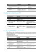
Figure 48 Network diagram for the MCE function
As shown in Figure 48, the MCE device creates a routing table for each VPN. VLAN interface 2 binds to
VPN 1 and VLAN-interface 3 binds to VPN 2. When receiving a route, the MCE device determines the
source of the routing information according to the number of the receiving interface, and then adds it to
the corresponding routing table. The MCE connects to PE 1 through a trunk link that permits packets
tagged with VLAN 2 or VLAN 3. PE 1 determines the VPN that a received packet belongs to according
to the VLAN tag of the packet, and sends the packet through the corresponding tunnel.
You can configure static routes, RIP, OSPF, IS-IS, EBGP, or IBGP between an MCE and a VPN site and
between an MCE and a PE.
NOTE:
To implement dynamic IP assi
g
nment for DHCP clients in private networks, you can confi
g
ure DHCP server
or DHCP relay agent on the MCE. The IP address spaces for different private networks cannot overlap.
MPLS L3VPN configuration task list
Tasks at a
g
lance
Configuring basic MPLS L3VPN
Configuring inter-AS VPN
Configuring nested VPN
Configuring HoVPN
Configuring an OSPF sham link
Configuring routing on an MCE
Specifying the VPN label processing mode on the egress PE
Configuring BGP AS number substitution
Enabling SNMP notifications for MPLS L3VPN