
HP MSR2000/3000/4000 Router Series MPLS Configuration Guide


165
Destinations : 13 Routes : 13
Destination/Mask Proto Pre Cost NextHop Interface
0.0.0.0/32 Direct 0 0 127.0.0.1 InLoop0
10.1.1.0/24 Direct 0 0 10.1.1.1 Eth1/1
10.1.1.0/32 Direct 0 0 10.1.1.1 Eth1/1
10.1.1.1/32 Direct 0 0 127.0.0.1 InLoop0
10.1.1.255/32 Direct 0 0 10.1.1.1 Eth1/1
10.2.1.0/24 BGP 255 0 10.1.1.2 Eth1/1
127.0.0.0/8 Direct 0 0 127.0.0.1 InLoop0
127.0.0.0/32 Direct 0 0 127.0.0.1 InLoop0
127.0.0.1/32 Direct 0 0 127.0.0.1 InLoop0
127.255.255.255/32 Direct 0 0 127.0.0.1 InLoop0
224.0.0.0/4 Direct 0 0 0.0.0.0 NULL0
224.0.0.0/24 Direct 0 0 0.0.0.0 NULL0
255.255.255.255/32 Direct 0 0 127.0.0.1 InLoop0
# CE 1 and CE 2 can ping each other.
Configuring MPLS L3VPN inter-AS option A
Network requirements
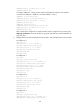
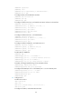
CE 1 and CE 2 belong to the same VPN. CE 1 accesses the network through PE 1 in AS 100, and CE
2 accesses the network through PE 2 in AS 200.
Configure inter-AS option A MPLS L3VPN, and use the VRF-to-VRF method to manage VPN routes.
Run OSPF on the MPLS backbone of each AS.
Figure 51 Network diagram
Device Interface IP address Device Interface IP address
CE 1 Eth1/1 10.1.1.1/24
CE 2
Eth1/1 10.2.1.1/24
Loop0 Loop0
Loop0 Loop0
POS5/1 POS5/1
POS5/0
POS5/0
POS5/0
POS5/0
Eth1/1
Eth1/1
Eth1/1
Eth1/1
CE 1 CE 2
AS 65001 AS 65002
PE 1
PE 2
ASBR-PE 2
ASBR-PE 1
MPLS backbone
MPLS backbone
AS 100
AS 200