
HP MSR2000/3000/4000 Router Series MPLS Configuration Guide


166
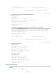
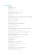
PE 1 Loop0 1.1.1.9/32
PE 2
Loop0 4.4.4.9/32
Eth1/1 10.1.1.2/24 Eth1/1 10.2.1.2/24
POS5/0 172.1.1.2/24
POS5/0 162.1.1.2/24
A
SBR-PE1 Loop0 2.2.2.9/32
A
SBR-PE2
Loop0 3.3.3.9/32
POS5/0 172.1.1.1/24 POS5/0 162.1.1.1/24
POS5/1 192.1.1.1/24
POS5/1 192.1.1.2/24
Configuration procedure
1. Configure IGP on the MPLS backbone:
This example uses OSPF. (Details not shown.)
After the configurations, each ASBR PE and the PE in the same AS can establish an OSPF
adjacency. Execute the display ospf peer command. The output shows that the adjacency has
reached the Full state, and that PEs can learn the routes to the loopback interfaces of each other.
Each ASBR PE and the PE in the same AS can ping each other.
2. Configure basic MPLS and MPLS LDP on the MPLS backbone to establish LDP LSPs:
# Configure basic MPLS on PE 1, and enable MPLS LDP on the interface connected to ASBR PE 1.
<PE1> system-view
[PE1] mpls lsr-id 1.1.1.9
[PE1] mpls ldp
[PE1-ldp] quit
[PE1] interface pos 5/0
[PE1-POS5/0] mpls enable
[PE1-POS5/0] mpls ldp enable
[PE1-POS5/0] quit
# Configure basic MPLS on ASBR PE 1, and enable MPLS LDP on the interface connected to PE 1.
<ASBR-PE1> system-view
[ASBR-PE1] mpls lsr-id 2.2.2.9
[ASBR-PE1] mpls ldp
[ASBR-PE1-ldp] quit
[ASBR-PE1] interface pos 5/0
[ASBR-PE1-POS5/0] mpls enable
[ASBR-PE1-POS5/0] mpls ldp enable
[ASBR-PE1-POS5/0] quit
# Configure basic MPLS on ASBR PE 2, and enable MPLS LDP on the interface connected to PE 2.
<ASBR-PE2> system-view
[ASBR-PE2] mpls lsr-id 3.3.3.9
[ASBR-PE2] mpls ldp
[ASBR-PE2-ldp] quit
[ASBR-PE2] interface pos 5/0
[ASBR-PE2-POS5/0] mpls enable
[ASBR-PE2-POS5/0] mpls ldp enable
[ASBR-PE2-POS5/0] quit
# Configure basic MPLS on PE 2, and enable MPLS LDP on the interface connected to ASBR PE 2.
<PE2> system-view
[PE2] mpls lsr-id 4.4.4.9
[PE2] mpls ldp