
HP MSR2000/3000/4000 Router Series MPLS Configuration Guide


181
Verifying the configuration
After the configurations, PE 1 and PE 2 can ping each other. Ping PE 2 from PE 1:
[PE1] ping -a 30.0.0.1 -vpn-instance vpn1 20.0.0.1
Ping 20.0.0.1 (20.0.0.1) from 30.0.0.1: 56 data bytes, press escape sequence to break
56 bytes from 20.0.0.1: icmp_seq=0 ttl=253 time=2.000 ms
56 bytes from 20.0.0.1: icmp_seq=1 ttl=253 time=1.000 ms
56 bytes from 20.0.0.1: icmp_seq=2 ttl=253 time=1.000 ms
56 bytes from 20.0.0.1: icmp_seq=3 ttl=253 time=1.000 ms
56 bytes from 20.0.0.1: icmp_seq=4 ttl=253 time=1.000 ms
--- Ping statistics for 20.0.0.1 ---
5 packet(s) transmitted, 5 packet(s) received, 0.0% packet loss
round-trip min/avg/max/stddev = 1.000/1.200/2.000/0.400 ms
Configuring MPLS L3VPN carrier's carrier
Network requirements
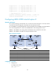
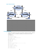
Configure carrier's carrier for the scenario shown in Figure 54. In this scenario:
• PE 1 and PE 2 are the provider carrier's PE routers. They provide VPN services for the customer
carrier.
• CE 1 and CE 2 are the customer carrier's routers. They are connected to the provider carrier's
backbone as CE routers.
• PE 3 and PE 4 are the customer carrier's PE routers. They provide MPLS L3VPN services for the end
customers.
• CE 3 and CE 4 are customers of the customer carrier.
The key to carrier's carrier deployment is to configure exchange of two kinds of routes:
• Exchange of the customer carrier's internal routes on the provider carrier's backbone.
• Exchange of the end customers' VPN routes between PE 3 and PE 4, the PEs of the customer carrier.
In this process, an MP-IBGP peer relationship must be established between PE 3 and PE 4.