
HP MSR2000/3000/4000 Router Series MPLS Configuration Guide


190
[PE1-LoopBack0] quit
[PE1] interface pos 5/1
[PE1-POS5/1] ip address 30.1.1.1 24
[PE1-POS5/1] isis enable 1
[PE1-POS5/1] mpls enable
[PE1-POS5/1] mpls ldp enable
[PE1-POS5/1] mpls ldp transport-address interface
[PE1-POS5/1] quit
[PE1] bgp 100
[PE1-bgp] peer 4.4.4.9 as-number 100
[PE1-bgp] peer 4.4.4.9 connect-interface loopback 0
[PE1-bgp] address-family vpnv4
[PE1-bgp-vpnv4] peer 4.4.4.9 enable
[PE1-bgp-vpnv4] quit
[PE1-bgp] quit
# Configure PE 2 in the same way that PE 1 is configured. (Details not shown.)
After completing the configurations, execute commands display mpls ldp peer, display bgp peer
vpnv4, and display isis peer on either PE 1 or PE 2. The output shows that the LDP session has been
established, the BGP peer relationship has been established and reached the Established state,
and the IS-IS neighbor relationship has been established.
Take PE 1 as an example:
[PE1] display mpls ldp peer
Total number of peers: 1
Peer LDP ID State LAM Role GR MD5 KA Sent/Rcvd
4.4.4.9:0 Operational DU Active Off Off 8/8
[PE1] display bgp peer vpnv4
BGP local router ID: 3.3.3.9
Local AS number: 100
Total number of peers: 1 Peers in established state: 1
Peer AS MsgRcvd MsgSent OutQ PrefRcv Up/Down State
4.4.4.9 100 3 6 0 0 00:00:32 Established
[PE1] display isis peer
Peer information for ISIS(1)
----------------------------
System Id: 0000.0000.0005
Interface: POS5/1 Circuit Id: 0000.0000.0005.02
State: Up HoldTime: 8s Type: L1(L1L2) PRI: 64
System Id: 0000.0000.0005
Interface: POS5/1 Circuit Id: 0000.0000.0005.02
State: Up HoldTime: 8s Type: L2(L1L2) PRI: 64
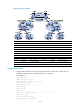
2. Configure the customer VPN—enable IS-IS and enable LDP between PE 3 and CE 1, and between
PE 4 and CE 2:
# Configure PE 3.