
HP MSR2000/3000/4000 Router Series MPLS Configuration Guide

194
# On CE 1, enable VPNv4 route exchange with PE 1.
[CE1] bgp 200
[CE1-bgp] address-family vpnv4
[CE1-bgp-vpnv4] peer 11.1.1.2 enable
# Allow the local AS number to appear in the AS-PATH attribute of the routes received.
[CE1-bgp-vpnv4] peer 11.1.1.2 allow-as-loop 2
# Disable route target based filtering of received VPNv4 routes.
[CE1-bgp-vpnv4] undo policy vpn-target
[CE1-bgp-vpnv4] quit
[CE1-bgp] quit
# Configure PE 2 and CE 2 in the same way that PE 1 and CE 1 are configured. (Details not
shown.)
6. Establish MP-IBGP peer relationships between sub-VPN PEs and CEs of the customer VPN to
exchange VPNv4 routes of sub-VPNs:
# Configure PE 3.
[PE3] bgp 200
[PE3-bgp] peer 2.2.2.9 as-number 200
[PE3-bgp] peer 2.2.2.9 connect-interface loopback 0
[PE3-bgp] address-family vpnv4
[PE3-bgp-vpnv4] peer 2.2.2.9 enable
# Allow the local AS number to appear in the AS-PATH attribute of the routes received.
[PE3-bgp-vpnv4] peer 2.2.2.9 allow-as-loop 2
[PE3-bgp-vpnv4] quit
[PE3-bgp] quit
# Configure CE 1.
[CE1] bgp 200
[CE1-bgp] peer 1.1.1.9 as-number 200
[CE1-bgp] peer 1.1.1.9 connect-interface loopback 0
[CE1-bgp] address-family vpnv4
[CE1-bgp-vpnv4] peer 1.1.1.9 enable
[CE1-bgp-vpnv4] undo policy vpn-target
[CE1-bgp-vpnv4] quit
[CE1-bgp] quit
# Configure PE 4 and CE 2 in the same way that PE 3 and CE 1 are configured. (Details not
shown.)
Verifying the configuration
After completing all the configurations, execute the display ip routing-table command on PE 1 and PE 2
to verify that the public routing tables contain only routes on the service provider network. Take PE 1 as
an example:
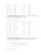
[PE1] display ip routing-table
Destinations : 14 Routes : 14
Destination/Mask Proto Pre Cost NextHop Interface
0.0.0.0/32 Direct 0 0 127.0.0.1 InLoop0
3.3.3.9/32 Direct 0 0 127.0.0.1 InLoop0