
HP MSR2000/3000/4000 Router Series MPLS Configuration Guide


205
[SPE2-bgp] address-family vpnv4
[SPE2-bgp-vpnv4] peer 4.4.4.9 upe route-policy hope export
Verifying the configuration
After completing all the configurations, CE 1 and CE3 can learn each other's interface routes and can
ping each other. CE 2 and CE 4 cannot learn each other's interface routes and cannot ping each other.
Configuring OSPF sham links
Network requirements
CE 1 and CE 2 belong to VPN 1 and are connected to PE 1 and PE 2.
CE 1 and CE 2 are in the same OSPF area.
VPN traffic between CE 1 and CE 2 is required to be forwarded through the MPLS backbone, instead of
through the backdoor route in the OSPF area.
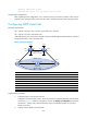
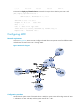
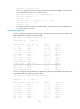
Figure 57 Network diagram
Device Interface IP address
Device
Interface
IP address
CE 1 Eth1/1 100.1.1.1/24
CE 2
Eth1/1
120.1.1.1/24
S2/1 20.1.1.1/24 S2/1 30.1.1.2/24
PE 1 Loop0 1.1.1.9/32
PE 2
Loop0
2.2.2.9/32
Loop1 3.3.3.3/32
Loop1
5.5.5.5/32
Eth1/1 100.1.1.2/24 Eth1/1 120.1.1.2/24
S2/1 10.1.1.1/24
S2/0
10.1.1.2/24
Router A S2/0 30.1.1.1/24
S2/1 20.1.1.2/24
Configuration procedure
1. Configure OSPF on the customer networks:
Configure conventional OSPF on CE 1, Router A, and CE 2 to advertise addresses of the interfaces
as shown in Figure 57. Aft
er the configuration, execute the display ip routing-table command to
see that CE 1 and CE 2 have learned the OSPF route to the Ethernet interface of each other.
(Details not shown.)
2. Configure MPLS L3VPN on the backbone:
S2/1
Loop0
Loop0
S2/0
Sham-link
Eth1/1
CE 1 Router A CE 2
PE 2PE 1
Eth1/1
S2/1 S2/1 S2/0 S2/1
Loop1 Loop1
Eth1/1
Eth1/1
OSPF Area 1
Backdoor link