
HP MSR2000/3000/4000 Router Series MPLS Configuration Guide

208
[PE2] bgp 100
[PE2-bgp] ip vpn-instance vpn1
[PE2-bgp-vpn1] address-family ipv4 unicast
[PE2-bgp-ipv4-vpn1] import-route ospf 100
[PE2-bgp-ipv4-vpn1] import-route direct
[PE2-bgp-ipv4-vpn1] quit
[PE2-bgp-vpn1] quit
[PE2-bgp] quit
After completing the configurations, execute the display ip routing-table vpn-instance command
on the PEs. The path to the peer CE is along the OSPF route across the customer networks, instead
of the BGP route across the backbone.
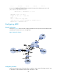
4. Configure a sham link:
# Configure PE 1.
[PE1] interface loopback 1
[PE1-LoopBack1] ip binding vpn-instance vpn1
[PE1-LoopBack1] ip address 3.3.3.3 32
[PE1-LoopBack1] quit
[PE1] ospf 100
[PE1-ospf-100] area 1
[PE1-ospf-100-area-0.0.0.1] sham-link 3.3.3.3 5.5.5.5 cost 10
[PE1-ospf-100-area-0.0.0.1] quit
[PE1-ospf-100] quit
# Configure PE 2.
[PE2] interface loopback 1
[PE2-LoopBack1] ip binding vpn-instance vpn1
[PE2-LoopBack1] ip address 5.5.5.5 32
[PE2-LoopBack1] quit
[PE2] ospf 100
[PE2-ospf-100] area 1
[PE2-ospf-100-area-0.0.0.1] sham-link 5.5.5.5 3.3.3.3 cost 10
[PE2-ospf-100-area-0.0.0.1] quit
[PE2-ospf-100] quit
Verifying the configuration
After completing the configurations, execute the display ip routing-table vpn-instance command again
on the PEs. The path to the peer CE is now along the BGP route across the backbone, and that a route
to the sham link destination address is present.
# Execute the display ip routing-table command on the CEs. The next hop of the OSPF route to the peer
CE is the Ethernet interface connected to the PE. This means that VPN traffic to the peer is forwarded over
the backbone.
# Execute the display ospf sham-link command on the PEs. The output shows that a sham link has been
established. Take PE 1 as an example:
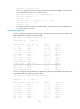
[PE1] display ospf sham-link
OSPF Process 100 with Router ID 100.1.1.2
Sham link
Area Neighbor ID Source IP Destination IP State Cost