
HP MSR2000/3000/4000 Router Series MPLS Configuration Guide

212
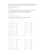
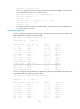
224.0.0.0/24 Direct 0 0 0.0.0.0 NULL0
255.255.255.255/32 Direct 0 0 127.0.0.1 InLoop0
The output shows that the MCE has learned the private route of VPN 2 through RIP. MCE maintains
the routes of VPN 1 and those of VPN 2 in two different routing tables. In this way, routes from
different VPNs are separated.
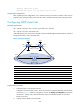
3. Configure routing between the MCE and PE 1:
# The MCE is connected to PE 1 through subinterfaces. On MCE, bind subinterface Ethernet 1/3.1
with the VPN instance vpn1, configure the subinterface to terminate VLAN 10, and configure an
IP address for the subinterface.
[MCE] interface ethernet 1/3.1
[MCE-Ethernet1/3.1] ip binding vpn-instance vpn1
[MCE-Ethernet1/3.1] vlan-type dot1q vid 10
[MCE-Ethernet1/3.1] ip address 20.1.1.1 24
[MCE-Ethernet1/3.1] quit
# On the MCE, bind subinterface Ethernet 1/3.2 with the VPN instance vpn2, configure the
subinterface to terminate VLAN 20, and configure an IP address for the subinterface.
[MCE] interface ethernet 1/3.2
[MCE-Ethernet1/3.2] ip binding vpn-instance vpn2
[MCE-Ethernet1/3.2] vlan-type dot1q vid 20
[MCE-Ethernet1/3.2] ip address 30.1.1.1 24
[MCE-Ethernet1/3.2] quit
# On PE 1, bind subinterface Ethernet 1/1.1 with the VPN instance vpn1, configure the
subinterface to terminate VLAN 10, and configure an IP address for the subinterface.
[PE1] interface ethernet 1/1.1
[PE1-Ethernet1/1.1] ip binding vpn-instance vpn1
[PE1-Ethernet1/1.1] vlan-type dot1q vid 10
[PE1-Ethernet1/1.1] ip address 20.1.1.2 24
[PE1-Ethernet1/1.1] quit
# On PE 1, bind subinterface Ethernet 1/1.2 with the VPN instance vpn2, configure the
subinterface to terminate VLAN 20, and configure an IP address for the subinterface.
[PE1] interface ethernet 1/1.2
[PE1-Ethernet1/1.2] ip binding vpn-instance vpn2
[PE1-Ethernet1/1.2] vlan-type dot1q vid 20
[PE1-Ethernet1/1.2] ip address 30.1.1.2 24
[PE1-Ethernet1/1.2] quit
# Configure the IP address of the interface Loopback0 as 101.101.10.1 for the MCE and as
100.100.10.1 for PE 1. Specify the loopback interface address as the router ID for the MCE and
PE 1. (Details not shown.)
# Enable OSPF process 10 on the MCE, bind the process to VPN instance vpn1, and set the
domain ID to 10.
[MCE] ospf 10 router-id 101.101.10.1 vpn-instance vpn1
[MCE-ospf-10] vpn-instance-capability simple
[MCE-ospf-10] domain-id 10
# Advertise subnet 20.1.1.0/24 in area 0, and redistribute the static route of VPN 1.
[MCE-ospf-10] area 0
[MCE-ospf-10-area-0.0.0.0] network 20.1.1.0 0.0.0.255
[MCE-ospf-10-area-0.0.0.0] quit